
G.Kleinschmidt said:Only 10 pairs?
Piece of cake for the bridged output stages of your 20KW project from the previous millenium, Mr G.
Still on the schedule to continue with that monster some day ?
(after the 502ci Rat, 540, 572, 700ci ?)
At least 1 who knows how to play movie charades.
Not more than 30 watts dissipation to each transistor
Each transistor will need aluminium plate to dissipate heat, if square plate, if 2 milimeters thick, 7 inches side (each one!)
Heatsink will have big refrigerator's size!... alike those tall home freezers.
Insanity is not a good word to describe....madness may fit better because we use to play music at 2 watts rms maximum!
Carlos
By Cbdb - 6 Kva at 220v = 27A in and 50A ish out at 120 V ? Is this right?
If the man is really going through with this - a 220v 4 prong
grounded electric range plug/socket with its own 40-50A
dedicated breaker would be the ticket.
An externally hosted image should be here but it was not working when we last tested it.
OS
jacco vermeulen said:Still on the schedule to continue with that monster some day ?
(after the 502ci Rat, 540, 572, 700ci ?)
Nup. No longer see any point in spending the $$$$ required to build a completed unit. Have moved on to power amplifiers of a different sort.
Not that you wouldn't know already, but the audio amplifier builds under way can be seen listed on my www.
Too busy working on the 2.25L at the moment. The 502 project well begin after I get that done and the blown 6 donk for the 260Z complianced and registered.
Any other questions?
Update..
got a "late" call from my supplier..
they cant find me anything under 3KVA, BUT the did find me a 7.5KVA that is used in medical power supplies ( i'm guessing MRI )
Plitron 7500VA Medical Isolation Transformer
BUT, they do have smaller versions online direct through them !!!
So, i will hate to look into that.
Also after reading through Fotios thread on Dirty Harry i stumbled across this reply and might be using MJL3281-MJL1302, which seem to be easier to design a driver board around and also easier to mount to a heat sink rather than the TO-3 packaged MJ21193/94.
I like the idea of putting the drivers sepparately due to heat dissapattion and make it easier for adding extra board or 2 or 3 if needed driven by the same output darlington. This way the the output board remains the same, and the driving board can be switched out with ease.
The one board that caught my attention though is the lynx 3.0 board
Also noticed that most Analog amps on here share the cascaded npn / pnp structure in most cases with very small variations to them.
ostripper said:
If the man is really going through with this - a 220v 4 prong
grounded electric range plug/socket with its own 40-50A
dedicated breaker would be the ticket.
An externally hosted image should be here but it was not working when we last tested it.
OS
Got one of thsoe on my distro. It's rare that you'll need one of those on an AMP. The 5000VZ is a horribly inefficient amp, running straight class AB and still only needs 30A under moderate clipping. It also only used 20 output transistors per channel and two 1kVA (continuous) trafos. Go class H and you can run less than 20A under heavy clipping with a LOT less heat! If the power supply is properly (over)built, those amps can be just as gutsy. It's a shame that the QSCs skimp on the trafos and reservoir banks.
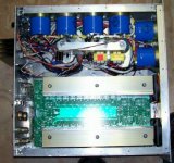
This is the one I'm working on so far (one of four, all at the same point). Main PCBs are unstuffed at this point, but I've been working on the wiring, rewinding trafos, and doing machine shop work with Home Depot tools 
+/-140V, 3 tier class H, 9 outputs per bank, 2 channels in 4U. 83% more transformer than the RMX5050, double the output dissipation capacity, and double the capacitance. Should put out an honest 2kW/ch at 2R.
+/-140V, 3 tier class H, 9 outputs per bank, 2 channels in 4U. 83% more transformer than the RMX5050, double the output dissipation capacity, and double the capacitance. Should put out an honest 2kW/ch at 2R.
Attachments
Adrculda said:Update..
got a "late" call from my supplier..
they cant find me anything under 3KVA, BUT the did find me a 7.5KVA that is used in medical power supplies ( i'm guessing MRI )
3kVA should be sufficient. They don't put anything that big in a store-bought amp, even a 5000VZ. If you want to save dough, put two or three standard off the shelf trafos in series. 1KVAs are around $100 new - less if you can find surplus. And don't be afraid of rewinding. It's hard, but not impossible.
QUOTE]Originally posted by Adrculda
Also after reading through Fotios thread on Dirty Harry i stumbled across this reply and might be using MJL3281-MJL1302, which seem to be easier to design a driver board around and also easier to mount to a heat sink rather than the TO-3 packaged MJ21193/94.[/QUOTE]
Exactly. And the TO-264 with no insulator (directly to heatsink) is better than TO-3 with insulator thermally. The flatpacks offer so much more options in terms of mounting that it may be possible to leave the heatsinks live (at rail potential, insulated from surroundings).
OMNIFEX said:
Hi Adrculda
I use EVX 180Bs in twelve double eighteen enclosures sitting on six Crown MA 5000vzs each getting 240 volts
Might I suggest 6-Gauge SO cable? I use that as speaker wire. It can withstand up to 600 Volts.
I use the spade lugs connections on the rear of the 5000s with neutrik speakons to connect to the subwoofers. Using cable with that type of density can easily handle 40 amps continuous.
Good luck on your design and, please post some photographs of the work in progress.
Cheers!
Ur running ur HF bins with that stuff too??
------------------------
Regarding the "stove/range/clothes dryer" 240VAC US/CAN plug?
Forget that. You won't find any place to plug it in, except in your laundry room - you'll be wanting a breakout box that gets connected to the incoming AC mains by an electrician before the show, and has "Twist-Loc" AC connectors. You want Twist-Loc connections, even on the input of your power amp, if it really sucks that much juice (easier to pack, carry, hook up, etc...). That's what pros use in North America (can't say about the rest of the world).
-----------------------
How many watts of power do you think you're gonna want out of this class A amp?? As Glen noted, if u want 1kw quiescent, you're into >3Kw of real heat... Let's think about that for a minute... find a "Quartz room heater" the ones with the big vertical elements? Glow red? They're only ~1kw. You gonna get rid of that heat with a fan on a heatsink?
-------------------------
Remote power supply?
Ur asking for problems.
If not oscillation, then very high IR drops, and also connection problems (current is so high, wire gauge so large).
-------------
Giant toroid??
Huh?
Why?
You can use multiple smaller toroids in parallel just fine.
Then when you realize how goofy this idea is in practical terms, you'll at least have 4-6 reasonable size toroids to resell or use in a set of practical Class AB amps...
(take a look through my website, amplifiers page, there is a shot of a nude amp chassis with 4 x 675va toroids = ~2.5kva)
------------------
Consider buying some of those MacroTechs (really high DF amps great for bass), or QSC or Crest or something else...multi-amp it, and building really great amps for your high end boxes - that's where all the carp is coming out of your PA from! You do know that?
Sorry to be quite so blunt on this... but it hurts to see someone thrashing about with a very expensive big project that is not very likely to have any good outcome - except for the builder's experience.
_-_-bear
On another thread Jacco mentioned that the Perreaux 5550 actually had a 6KVA tranformer (or tranformer set?).
I don't know whether that would qualify as a "store bought" amp, though.
For the project that's the subject of this thread, though, I'm not sure I understand the practicality of building an amp for portable DJ use that you won't be able to plug into most outlets. Next step, a generator?
I don't know whether that would qualify as a "store bought" amp, though.
For the project that's the subject of this thread, though, I'm not sure I understand the practicality of building an amp for portable DJ use that you won't be able to plug into most outlets. Next step, a generator?
wg_ski said:This is the one I'm working on so far (one of four, all at the same point). Main PCBs are unstuffed at this point, but I've been working on the wiring, rewinding trafos, and doing machine shop work with Home Depot tools
+/-140V, 3 tier class H, 9 outputs per bank, 2 channels in 4U. 83% more transformer than the RMX5050, double the output dissipation capacity, and double the capacitance. Should put out an honest 2kW/ch at 2R.
Looks like you do nice work!
However, I'm wondering if you can really get 2kw out of even a single channel for very long? Unless the scale of things is fooling my eye, you don't have enough transformer or filtering to hold up the rails, keep the rail from sagging, and very high ripple appearing? I guess there are enough output devices... but just considering rated at 500w/ch at 8 ohms I'd be wondering if the PS can keep up with the task... peak, low duty cycle, sure.
_-_-bear
PS. You haven't fired up the PS yet? You might have a problem with the way you mounted the toroids? That looks like a metal loop forming a shorted turn through the center of the toroids? Hard to see for sure...
It will only need to produce 2kW/ch for a few minutes. Heck, an old CS-800 boat anchor can only put out full sine wave for a few minutes before overheating, and that's a lot longer than a moden amp will! But I expect 1/8 power with pink noise at 2 ohms or 1/3 power at 4 to run continuously with the amount of heatsink and trafo. That will shut down a QSC after 15 minutes - the most they'll take is 1/8 power at 4 ohms continuously. The RMX5050 uses two 600VA trafos! Mine are 1100 each. And yes, you can pull ten times their rated VA for a few minutes at at time. Power supply sag is down to +/-100V at 35A - which will support full power. Those caps are 68000 uF each, which gives the required 20,000 when 3 are in series.
The shorted turn is one of those little details you have to figure out as you go along. Luckily, I've already figured out how to isolate the (rail potentail) heat sinks and that gave me ideas how to break the loop. It was an even bigger challenge to figure out how to bolt the trafos down without the hex head sticking out the bottom of the chassis.
The shorted turn is one of those little details you have to figure out as you go along. Luckily, I've already figured out how to isolate the (rail potentail) heat sinks and that gave me ideas how to break the loop. It was an even bigger challenge to figure out how to bolt the trafos down without the hex head sticking out the bottom of the chassis.
Dunno about minutes... was thinking in msecs...
But I guess if you really have dual 1.1kva iron, I guess it is bigger than the image makes it look...
you can't have a shorted turn through the toroids. Break the rail on the top. It's a magnetic loop, not electrical.
mounting toroids is often a challenge - keeping them from sliding around in the case of a drop is also an issue, unless the center hole is epoxy potted/filled....
so what did you do to keep the hex from sticking out the bottom?
one way to go is with a carriage bolt, smoother.
another way to go - but much harder to find - is an "elevator bolt" they have thin flat heads...
_-_-bear
bear said:
Ur running ur HF bins with that stuff too??
------------------------
_-_-bear
I don’t need that type of current for my high frequency bins.
 I am assuming you are referring to mid range as well?
 QSC EX 4000s take cares of everything starting from 100 Hertz – 20 kHz. Although, the protection circuitry embedded in the amplifier begins to limit the output above 15 kHz. I don’t mind at all for I am allergic to 17 kHz.
 For the cabling, I use 10-gauge which is more than enough for the amplifier only delivers 1200 watts per channel in a 4-ohm load.
I do however, switch to the QSC PL 6.0s when I need a little more power when I am doing a really big event. But I must say, the EX 4000s are usually fine 80% of the time.
For smaller events I take my Peavey CS 800s and, use 10-Gauge cabling. Those are bridged and only used for bass. I prefer high-current amplifiers for bass and non-heavy-current amplifiers for Mid/Highs.
Cheers!
"Why is the lightbulb still ON? And why is the mounting rail for the supervisor PCB getting HOT?????" It ended up getting insulated with bushings the same way the heat sinks did. There are two PCBs there, stacked on top of one another. All 4 heat sinks are electrically live, and since this is rail switched, none can be common.
Mounting the toroids - Three #8-32 flat-head machine screws are flush mounted through the bottom of the chassis, supporting a metal "coin" that the hex bolt also goes through. The previous iteration was a block of wood, but I decided to get that out of there.
To the OP on this thread - you see what kinds of fun you'll have to deal with on a project liek this yet? Not scared off yet, are you?
if the thing that is getting hot is that aluminum bar that goes between the two toroids, it is because you have a magnetic circuit, not an electrical one?
otherwise it is unclear what it is that is getting hot...
dunno why you have a light staying on... heh.
_-_-bear
PS. Omni - i was wondering because of the self inductance of the #6... just checking...
otherwise it is unclear what it is that is getting hot...
dunno why you have a light staying on... heh.
_-_-bear
PS. Omni - i was wondering because of the self inductance of the #6... just checking...
bear said:
Sorry to be quite so blunt on this... but it hurts to see someone thrashing about with a very expensive big project that is not very likely to have any good outcome - except for the builder's experience.
_-_-bear
I look at is as constructive criticism, and also you guys are giving me great ideas on how to maximize my budget which i have set aside about $2500. if i can get even more out of it than that's even better !!!
wg_ski said:
To the OP on this thread - you see what kinds of fun you'll have to deal with on a project liek this yet? Not scared off yet, are you?
Nope...
my grandfather before he passed away said a couple of words to me that opened m teenage eyes ( at the time ) most of the not pertaining to anything here but one:
"A smart man learns from other peoples mistakes"
- Status
- This old topic is closed. If you want to reopen this topic, contact a moderator using the "Report Post" button.
- Home
- Amplifiers
- Solid State
- Building a Monster... Class A