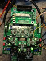
While waiting for the NTD1 GB, I start to connect all the control modules together. Today I modified the SideCar and directly plug it onto the BIII without using the flat cable. Also solder the U.FL socket to the PCM/DSD input.
WaveIO will be connected to FIFO through the SPDIF backdoor. OTTO2 will be used to select between FIFO and DSD.
My plan is to modify a SACD player to output DSD signal and connect to BIII via Teleporter.
I've joined the GB for the USB to I2S DSD converter, may be this converter has to route through the Teleporter as I don't have so many inputs
Does anyone has experience to power the WaveIO by LiPO battery? Can I use two diodes to drop the voltage from 6.4 to around 5V? Will this affect the SQ?
Attachments
If 6.2 is actually the max voltage you'll see from the lipos and not just the nominal voltage, then I would think you would be able to simple connect it, cant see the regs being too troubled by an extra volt.
Yeah, I agree, normally you would think that an extra volt 'should' be ok, but, I asked the question to be sure and here is an extract of an email from Lucian:
Hello Chris,
below is a list of all the Vreg Chips that are used in WaveIO card, all
of them are wired together in parallel AFTER the protection diode:
TPS71710
LP3879 - 1.0
LP3982 - 3.3
TPS76318
LP5900 - 3.3
Please see the datasheet for me since it will answer to all of your
questions. The series diode has the dropout voltage of ~0.4V
From what I remember few regs will not withstand to more than 6V but
please read the specs to be sure.
So if you rely on the on board diode you may well get from 6.2 to 5.8 and be ok, but you've got to be diligent and be sure that you never connect more than 6V to 6.2V the input, very little room for error there it seems. Some of the chips might live with a touch over their datasheet spec, but it's not how I would want to live on a day-to-day basis.
High marks to you and your progress bigpandahk! I got my Arduino UNO with 4x20 lcd going but it doesn't let my dual BIII sing. The code drives me crazy!
Do you connect the I2C bus correctly with the level converter? Remember to remove the on-board firmware.
Does the Lock LED on BIII light up? if yes, you may put a jumper to short PB4 to 3.3V to see if the Arduino mute the BIII.
Do you connect the I2C bus correctly with the level converter? Remember to remove the on-board firmware.
Does the Lock LED on BIII light up? if yes, you may put a jumper to short PB4 to 3.3V to see if the Arduino mute the BIII.
Thanks for the suggestions. Yes on the level converter, this one
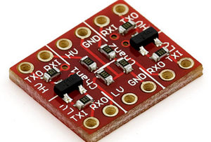
I followed this HiFiduino wiring diagram
http://hifiduino.files.wordpress.com/2010/10/i2c1.jpg
yes on removing the firmware chip. No lock LED using coax input. I am using the Twisted Pear 4-Channel S/PDIF input board through Sidecar. I tried all inputs with selector and also moving input on S/PDIF board. No code for Sidecar entered yet. Sidecar not triggered so input should pass through.
Does your BIII works without Arduino?
Yes. Both before and after trying Arduino (firmware chip reinstalled).
Time for rest, I'll look at it again tomorrow.
Thanks for the suggestions. Yes on the level converter, this one
I followed this HiFiduino wiring diagram
http://hifiduino.files.wordpress.com/2010/10/i2c1.jpg
yes on removing the firmware chip. No lock LED using coax input. I am using the Twisted Pear 4-Channel S/PDIF input board through Sidecar. I tried all inputs with selector and also moving input on S/PDIF board. No code for Sidecar entered yet. Sidecar not triggered so input should pass through.
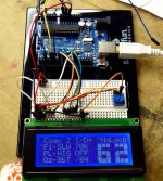
Can your Arduino Sketch select the source format? Make sure SPDIF is selected.
From your photo, I2S/DSD format is selected instead of SPDIF.
Last edited:
HiFiDuino's code does not support multiple inputs / switching between inputs.
If your source is not connected to the first input (if I remember correctly) it will not be properly selected.
TP's selector relies on the on-board firmware to make the switching (essentially to write the correct values into the 9018's registers), so if you have removed the firmware it will not work.
The solution would be to alter the code so that it supports proper switching between sources (in essense setting the necessary registers). I can help with that, and so can most of the people around here.
For example, try doing something like this:
(The above code is a sample, to give you an idea. Ignore the myGLCD stuff.. I'm using a different display)
If your source is not connected to the first input (if I remember correctly) it will not be properly selected.
TP's selector relies on the on-board firmware to make the switching (essentially to write the correct values into the 9018's registers), so if you have removed the firmware it will not work.
The solution would be to alter the code so that it supports proper switching between sources (in essense setting the necessary registers). I can help with that, and so can most of the people around here.
For example, try doing something like this:
Code:
void setAndPrintInput(byte value){
  setAndPrintInputFormat(settings[input][FORMATVAL]%FORMATCHO);  // Setup input format value
  setAndPrintFirFilter(settings[input][FIRVAL]%FIRCHO);          // Setup FIR filter value
  setAndPrintIirFilter(settings[input][IIRVAL]%IIRCHO);          // Setup IIR filter value
  setAndPrintDPLL(settings[input][DPLLVAL]%DPLLCHO);             // Setup the DPLL value
  setAndPrintQuantizer(settings[input][QUANVAL]%QUANCHO);        // Setup quantizer value
  setAndPrintNotch(settings[input][NOTCHVAL]%NOTCHCHO);          // Setup notch delay value
  setAndPrintDPLLMode(settings[input][PLMVAL]%PLMCHO);            // Setup dpll mode value

  myGLCD.setFont(DotMatrix_M);
  myGLCD.setColor(0, 100, 255);
  myGLCD.print("Input:", 200, 32);

  switch (value){
  case 0:
    writeSabreReg(0x12,0x01);        // Set SPDIF to input #1
    myGLCD.print(no0, 200, 60);
    break;
  case 1:
    writeSabreReg(0x12,0x02);        // Set SPDIF to input #2
    myGLCD.print(no1, 200, 60);
    break;
  case 2:
    writeSabreReg(0x12,0x04);        // Set SPDIF to input #3
    myGLCD.print(no2, 200, 60);
    break;
  case 3:
    writeSabreReg(0x12,0x08);        // Set SPDIF to input #4
    myGLCD.print(no3, 200, 60);
    break;
  case 4:
    writeSabreReg(0x12,0x10);        // Set SPDIF to input #5
    myGLCD.print(no4, 200, 60);
    break;
  case 5:
    writeSabreReg(0x12,0x20);        // Set SPDIF to input #6
    myGLCD.print(no5, 200, 60);
    break;
  case 6:
    writeSabreReg(0x12,0x40);        // Set SPDIF to input #7
    myGLCD.print(no6, 200, 60);
    break;
  case 7:
    writeSabreReg(0x12,0x80);        // Set SPDIF to input #8
    myGLCD.print(no7, 200, 60);
    break;
  }
}
(The above code is a sample, to give you an idea. Ignore the myGLCD stuff.. I'm using a different display)
Yeah, I agree, normally you would think that an extra volt 'should' be ok, but, I asked the question to be sure and here is an extract of an email from Lucian:
So if you rely on the on board diode you may well get from 6.2 to 5.8 and be ok, but you've got to be diligent and be sure that you never connect more than 6V to 6.2V the input, very little room for error there it seems. Some of the chips might live with a touch over their datasheet spec, but it's not how I would want to live on a day-to-day basis.
Thanks qusp and hochopeper.
I checked the data sheets for all the regulators and two of them can only accept 6.0V max input voltage. I need at least one or two diodes in series with the battery as the max voltage will be 6.6V when fully charged.
hmm well thats pretty lame, sorry about that, I would not have predicted such a narrow input voltage range for LDOs. I dont have the time or inclination to look up all the datasheets to see which, but i'm guessing the 1.2v maybe wont like it?, even though similar LDO regs from lineartech will cope with that and MUCH more, usually thats one of the advantages of using these LDOs, having a wide input voltage range.
seems counterproductive to go to the trouble of using batteries and then connect them to 2-3 diodes in series and a bunch of LDOs, so if it were me, I wouldnt bother. I would be more likely to check thresholds for the clocks and clock buffers, then connect suitable regs or batteries directly to the important supplies and bypass the onboard regs. specifically for the clocks. its pretty easy to find batteries that are 3.3-3.5vdc
HiFiDuino's code does not support multiple inputs / switching between inputs.
(The above code is a sample, to give you an idea. Ignore the myGLCD stuff.. I'm using a different display)
Thanks DimDim, I have put your suggestion into ScompRacer's code and hope it help.
hmm well thats pretty lame, sorry about that, I would not have predicted such a narrow input voltage range for LDOs. I dont have the time or inclination to look up all the datasheets to see which, but i'm guessing the 1.2v maybe wont like it?, even though similar LDO regs from lineartech will cope with that and MUCH more, usually thats one of the advantages of using these LDOs, having a wide input voltage range.
seems counterproductive to go to the trouble of using batteries and then connect them to 2-3 diodes in series and a bunch of LDOs, so if it were me, I wouldnt bother. I would be more likely to check thresholds for the clocks and clock buffers, then connect suitable regs or batteries directly to the important supplies and bypass the onboard regs. specifically for the clocks. its pretty easy to find batteries that are 3.3-3.5vdc
No need to say sorry ah! Without your help and advice, I won't have such good progress
I agree with you that so many diodes + LDO is not a good solution. At the moment, I will power the BIII + WaveIO with SSLV and modify it to battery powered later.
hmm well thats pretty lame, sorry about that, I would not have predicted such a narrow input voltage range for LDOs. I dont have the time or inclination to look up all the datasheets to see which, but i'm guessing the 1.2v maybe wont like it?, even though similar LDO regs from lineartech will cope with that and MUCH more, usually thats one of the advantages of using these LDOs, having a wide input voltage range.
seems counterproductive to go to the trouble of using batteries and then connect them to 2-3 diodes in series and a bunch of LDOs, so if it were me, I wouldnt bother. I would be more likely to check thresholds for the clocks and clock buffers, then connect suitable regs or batteries directly to the important supplies and bypass the onboard regs. specifically for the clocks. its pretty easy to find batteries that are 3.3-3.5vdc
Honestly, I haven't looked up the datasheets since about May/June this year, since I didn't write any notes at the time and my eidetic memory is still on backorder from Big PharmaceuticalTM, I can't remember exactly which ones were the issue.
Regardless, if you're feeding the signal into the FIFO, does bypassing the onboard regs for the NDK crystals on the WaveIO have a big potential for improvement to the signal out of the end? I vote put the best regs you can on the clock board of the FIFO and a good, but not overkill PSU on the WaveIO and don't sweat it too much more than that
All of this hassle for constantly diminishing return is why I went to a LT1085 pre-reg for the WaveIO and stopped worrying about it
. Best solution I can think of is to use isol spdif output from waveio and feed into spdif of FIFO. Or if you really want to isol i2s. Or use Ian's intermediate isolator board. So with that in mind, then aren't we really focussing on the wrong end of the line here for significant improvements?
Last edited:
Regardless, if you're feeding the signal into the FIFO, does bypassing the onboard regs for the NDK crystals on the WaveIO have a big potential for improvement to the signal out of the end? I vote put the best regs you can on the clock board of the FIFO and a good, but not overkill PSU on the WaveIO and don't sweat it too much more than that
All of this hassle for constantly diminishing return is why I went to a LT1085 pre-reg for the WaveIO and stopped worrying about it
Best solution I can think of is to use isol spdif output from waveio and feed into spdif of FIFO. Or if you really want to isol i2s. Or use Ian's intermediate isolator board. So with that in mind, then aren't we really focussing on the wrong end of the line here for significant improvements?
Originally, I connect the WaveIO to spdif of FIFO but it doesn't work. They work perfectly when connect WaveIO to the backdoor I2S of FIFO. I don't have another SPDIF source to identify the source of problem.
I found that the PSU for the Arduino also seriously affect the SQ.
I found that the PSU for the Arduino also seriously affect the SQ.
What exactly do you mean by this? Are you using the Arduino's PSU for powering something else besides the Arduino?
Is it a proximity thing? Are we talkin' interference?
What exactly do you mean by this? Are you using the Arduino's PSU for powering something else besides the Arduino?
Is it a proximity thing? Are we talkin' interference?
Since all of digital grounds join, control ground and digital input signal ground, then the noise from one propagates on the ground plane and impacts the signal integrity of the i2s.
Since all of digital grounds join, control ground and digital input signal ground, then the noise from one propagates on the ground plane and impacts the signal integrity of the i2s.
How about Isolating i2c bus (incl.gnd) ?
I have been using adum 1250 for isolating i2c between BII and arduino, and stop
worrying about noise from arduino+display.
Last edited:
Yes, in addition to the noise from the ground plane, I used the Arduino digital out to control the OTTO II may be another source of interference. I will change it to relay interface and directly short the two control pins to the power supply for OTTO with serious resistor.
Both the I2C and the connection to FIFO need to be isolated.
Both the I2C and the connection to FIFO need to be isolated.
Last edited:
- Status
- This old topic is closed. If you want to reopen this topic, contact a moderator using the "Report Post" button.
- Home
- Source & Line
- Digital Line Level
- Build Thread for TPA BIII + Ian Async I2S FIFO + OPC NTD1 + Salas SSLV