Hi Guys
Despite reading the whole thread, I'am in the dark. I build two dac (at the same time, which is stupid I know, I should have started with one the the other ...).
At first both were having problem with Q2 (V around 0 on ess pin 11), Q2 were not correctly oriented (My fault I only used the picture in the first page of the thread instead of looking at the datasheet). I manage to resolder both Q2 and now all the voltage on both ess are good. One of the board had bad voltage on all wm8804 pins, I destroyed it trying removing excessive solder on wm8804 legs.
The other board is not working (no sound, perfect silence) : On WM8804 I got 1,83 V on leg 9 instead of 0V, 0,81V on leg 10 instead of à,52 and 1,50V on leg 13 instead of 0,83V. Everything looks good on the dac side. I tried using Q1 from the board I destroyed and I got the exact same voltage.
Does anyone has any idea on what could be wrong ?
Thanks
Last edited:
A happy builder here, with DAC firing up first time. I'm a novice builder but managed it with a fat screw driver type tip soldering iron.
Sorry to bring up C17 again, but seeing as there are recommendations for a ceramic, I have two values of X7Rs in hand that are destined for another project I'm planning, they are 10uF or 100nF. Would either be suitable of is it worth getting the 1uF as recommended?
Thanks for all efforts on the PCB and group buy.
Edit: Bob that's good you updated the first post with correct orientation for the oscillator, people like me will find that really useful. I had it correct first time, then went back and changed orienation when reading your post (before you had updated it), then later saw error of my way and unsoldered it a second time. It took quite a bit of heat to remove the second time, but seems to be working ok. Is it a case of either working or not, or could the excess heat have caused some damage?
Hours of talk about the power LED ? C17 ? Connectors ?
Sorry to bring up C17 again, but seeing as there are recommendations for a ceramic, I have two values of X7Rs in hand that are destined for another project I'm planning, they are 10uF or 100nF. Would either be suitable of is it worth getting the 1uF as recommended?
Thanks for all efforts on the PCB and group buy.
Edit: Bob that's good you updated the first post with correct orientation for the oscillator, people like me will find that really useful. I had it correct first time, then went back and changed orienation when reading your post (before you had updated it), then later saw error of my way and unsoldered it a second time. It took quite a bit of heat to remove the second time, but seems to be working ok. Is it a case of either working or not, or could the excess heat have caused some damage?
Last edited:
looking at the schematic I was thinking my problem on wm88804 come from Q1, but having trying two of them and getting the same voltage problem I really don't know. I have double check every solder joint, all voltage at regulator and other vm8804 legs and everything is normal.
I was so worried about Q2 and ess9023 and, it's the working part of my dac !
I was so worried about Q2 and ess9023 and, it's the working part of my dac !
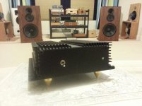
I finish testing my V3, everything is spot on and have it running for about 4 hours. It sounds smooth, a little laidback, but the sound stage is dark n wide. I let it run for another 100 hours before serious compare with my Audionote 2.1
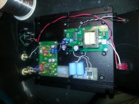
Attachments
Bcmbob, sorry for not being clear.
Both board are not working. One is "dead" as I lifted some pcb traces while resoldering wm8804.
The other one looks ok but doesn't play music. On this board checking the voltage against Atupi value (post #256) everything is good except for legs 9,10 and 13 of wm8804. I first suspected Q1, but I tried using Q1 from the "dead" board and I got the exact same value.
Last edited:


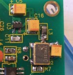
Q2 was soldered with a wrong orientation, while desoldering it (with my basic iron) I accidentally tear the pad on the upper right side. I used a flattened piece of copper wire to make a new track between the cap and L3 and soldered Q2 on it. That's why Q2 is is shifted right. I checked all the continuity and amazingly everything is ok and I get all the right voltage on the dac pin. So I think my problem is coming from the receiver part.
I'll give some time for burn in and later compare it to Benchmark and other diy Wolfson DAC.
as promised here is a brief review after 50h+ of burn in time:
1. Good, very good, especially bearing in mind that the whole project was about 50 quid for me, except the case.
2. Step above my other WM8740 DAC (diy kit from ebay) with 4 Salas regs. Soundstage is considerably wider. That was the main point here.
3. Regarding Benchmark, the first thing that came into my mind after 5-10 seconds was where the hell are highs?! It's like everything above 10khz is slightly cut and is quite smooth, not as articulated as on Benchmark. Second, the sounstage is not that big and you feel the limit, it's only between the speakers. The last point was Metallica's drummer. When you listen to first seconds of "My world", it's like Lars is playing only on one drum.
Tried to stay with the bom, but as I've already had some decent parts from the other projects and repairs I used them. C17 was swapped with ceramic. I suppose better results could be gained if parts would be 100% as thoroughly selected by JP, though anyway I'm happy with the project and it's damn good!

Hello all,
not yet started the project but can you tell me if these amplifiers are OK for the PSU.
(i got 2 PSU to build)
LOT DE 3 Transformateurs Pour Ampli Casque À Lampes ECC82 OU 6SN7 | eBay
not yet started the project but can you tell me if these amplifiers are OK for the PSU.
(i got 2 PSU to build)
LOT DE 3 Transformateurs Pour Ampli Casque À Lampes ECC82 OU 6SN7 | eBay
Hey dtses, thanks - just curious about your source. Are you listening to SACD or Hi-Def tracks? I assume you are.
cheers Bob,
the source was T+A cd1210, I've upgraded the caps and added clock here. Turned out to be a step over Benchmark if we would compare the dacs, bad point it skips sometimes.
Non standard build but it's impressive enough when it's better than a WM8740 DAC with 4 Salas regs. It should be
Otherwise I can not judge a thing when other parts were used.
It's noticeably better, very beautiful and carefully designed
")
I used silmics for dac and nichicon fw in PS, the rest should be as per bom. Hope I didn't loose too much with that configuration.
Hello all,
not yet started the project but can you tell me if these amplifiers are OK for the PSU.
(i got 2 PSU to build)
LOT DE 3 Transformateurs Pour Ampli Casque À Lampes ECC82 OU 6SN7 | eBay
I only see an erreur when I click on that link. Please just use the recommended one. It is cheap and good.
Since you have the Salas Shunt reg already, try it out, just make sure it is around 5V. You may find some hidden potential of DacI used silmics for dac and nichicon fw in PS, the rest should be as per bom. Hope I didn't loose too much with that configuration.
- Home
- Source & Line
- Digital Line Level
- Build thread - building the Subbu DAC V3 SE