I strung together yellow Christmas lights to get about 1.6pF for the feedback cap...
Hi Blues,
This is a concept I'm not familiar with; can you explain what your doing with those "yellow Christmas lights"?
John
")
Blues said:
note that I strung together yellow Christmas lights to get about 1.6pF for the feedback cap
carpenter said:
This is a concept I'm not familiar with;
can you explain what your doing with those "yellow Christmas lights"?
I also want to know, Blues
I sure I will get it, as soon as you tell a bit more
... yellow LED to about 1.6pF for the feedback capacitor ...
To get very small caps,
I sometimes take two short pieces of insulated wires (5-15mm of length)
and twist them together
This makes a very small picoFarad cap,
you attach the two 'pins' at one end of this twisted pair
to make the capacitor pins for solder at PCB
lineup
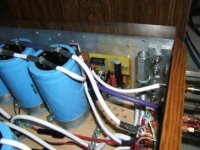
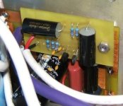
Sorry for the confusion John and Lineup. The "yellow Christmas lights" I was refering to was the 6 little 10pF caps (that look like little yellow bulbs) that I connected in series to get my desired 1.6pF. I had thought about the twisted wires as mentioned by NP but I didn't have an oscilloscope to really check out the square waves. With the 10pF caps it was more definitive. The simulation indicated <2pF corrects for overshoots on the leading edges and looks good up to 50kHz. More than 2pF have it too rounded. Simulation also indicates removal of high frequency distortion on the sine waves with this value of feedback cap.
Anyway I'm attaching the circuit as built and as measured.
Attachments
Blues said:
I had thought about the twisted wires as mentioned by NP
............
Anyway I'm attaching the circuit as built and as measured.
So Nelson mentioned this too, before me.
I did not know.
But this way to make very small home built plastic film capacitors
is often used within RF radio frequency circuits.
The insulation of wire is of plastic.
This makes it a plastic film cap, where the material in insulation is the separator.
If you use PVC normal insulated wire, it will be a
PolyVinylCloride Cap.
If you use PolyEthene insulated wire, cap will a
PolyEthene Cap.
And so on .......
It can still have some other and maybe better qualities than small ceramic caps.
As whatever plastic, it still is a so called film cap.
But for such small capacitances, the cap quality will not effect the audio band almost nothing.
They are for very high ( RF ) fequencies and maybe stability issues.
The quantity of capacitance is the thing = the value in pF.
Rather than any quality of this very small capacitance.
lineup
Carpenter,
The cascoded jfet buffer is to me a very worthwhile upgrade...a bit of effort for a really big improvement. I used to miss the Aleph 3's fine top-end using the Zv4 but the Blues Buffer's Brother (B^3) changed all that. The Zv4jC sound now really gives the A3 a run for its money.
Allan
Big Thanks to Mr. Pass for the jfet buffer circuit and to Steen for the jfets and for calling it Blues Buffer (B^2).
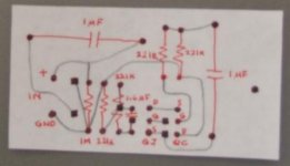
Here's the pcb design drawn by hand...
The cascoded jfet buffer is to me a very worthwhile upgrade...a bit of effort for a really big improvement. I used to miss the Aleph 3's fine top-end using the Zv4 but the Blues Buffer's Brother (B^3) changed all that. The Zv4jC sound now really gives the A3 a run for its money.
Allan
Big Thanks to Mr. Pass for the jfet buffer circuit and to Steen for the jfets and for calling it Blues Buffer (B^2).
Here's the pcb design drawn by hand...
Attachments
Here's the pcb design drawn by hand...
A bit out of focus, my friend. Can you enlarge the picture?
So.. I haven't read much about the BoSoZ yet because I have to learn some Linear algebra first.
I just wanna know: if I would build a BoSoZ for my Zen V4.. how would I connect it to unbalanced soures/amps?
The green lines, right?
I just wanna know: if I would build a BoSoZ for my Zen V4.. how would I connect it to unbalanced soures/amps?
An externally hosted image should be here but it was not working when we last tested it.
The green lines, right?
Carpenter,
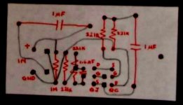
I'm reposting the picture of the pcb design. I hope it's much better. The square dots (sounds like balanced/single-ended are where the pins/stilts connect to the stock Zv4 pcb and the one in the middle of the 1.6uF cap is the jumper wire connection of the feedback. Note that the feedback is now taken before the output caps. Also, referring to the Zv4 circuit, remove Q4, R13(replace with 2.2k/3W), R3, C12 and R20(replace with jumper).
I think I posted the mirror image -if that's the case just trace the reverse image.
Luda,
I think diyers with a BOSOZ can comment better than I can. Anyone, please?
Allan
I'm reposting the picture of the pcb design. I hope it's much better. The square dots (sounds like balanced/single-ended
are where the pins/stilts connect to the stock Zv4 pcb and the one in the middle of the 1.6uF cap is the jumper wire connection of the feedback. Note that the feedback is now taken before the output caps. Also, referring to the Zv4 circuit, remove Q4, R13(replace with 2.2k/3W), R3, C12 and R20(replace with jumper).I think I posted the mirror image -if that's the case just trace the reverse image.
Luda,
I think diyers with a BOSOZ can comment better than I can. Anyone, please?
Allan
Attachments
lineup said:The insulation of wire is of plastic. This makes it a plastic film cap,
where the material in insulation is the separator. If you use PVC
normal insulated wire, it will be a PolyVinylCloride Cap. If you use
PolyEthene insulated wire, cap will a PolyEthene Cap.
I use Teflon insulated wire-wrap wires.
Blues said:
The cascoded jfet buffer is to me a very worthwhile upgrade...a bit of effort for a really big improvement. I used to miss the Aleph 3's fine top-end using the Zv4 but the Blues Buffer's Brother (B^3) changed all that. The Zv4jC sound now really gives the A3 a run for its money.
Blues,
Thanks for bringing to light this excellent thread again, it is till a very attractive proposition.
Now that you have had more time to evaluate this jfet cascoded “Buffer for Blues” circuit could you summarize your impressions on the sound and maybe compare it to some other amps you may have around?
As I recall you were favorable impressed about mid and HF sweetness but you were somewhat elusive describing bass performance, could you elaborate a bit more on the subject?
Is this amp still your preference for the main system you may have?
Hi Tony,
It's been almost a year since I made the upgrade and has enjoyed the Zv4jC every second it's turned on. Every time I'm not home the amp seems to be saying in Norah Jones' singing voice, "I'm just sitting here, waiting for you to come on home and turn me on".
With the new buffer the bass is more defined (sounds solid with a 2 1/2 design 2x5.5" mid/woofer) and fills up the 16'x16'x9' listening room nicely. It even vibrates slightly the wood flooring at moderate to loud levels. I did not elude describing the bass earlier but concentrated on the mid to high response because this is where the most improvement occured...and IMHO where the B^3 really shines. Incidentally I was playing around with the circuit sim and it shows a flat response up to about 350kHz. The Zv4 is -3db down at about 40kHz. My speakers have aluminum tweeters but they do not exhibit harshness with the extended highs.
I regularly switch back to the stock Aleph 3 and I can say the sound is much closer now. Sweetness though is with the Zv4jC -could be the higher 2nd harmonics. Summer temps has prevented me from running it too long even with additional copper plates on the heatsinks.
It's been almost a year since I made the upgrade and has enjoyed the Zv4jC every second it's turned on. Every time I'm not home the amp seems to be saying in Norah Jones' singing voice, "I'm just sitting here, waiting for you to come on home and turn me on".
With the new buffer the bass is more defined (sounds solid with a 2 1/2 design 2x5.5" mid/woofer) and fills up the 16'x16'x9' listening room nicely. It even vibrates slightly the wood flooring at moderate to loud levels. I did not elude describing the bass earlier but concentrated on the mid to high response because this is where the most improvement occured...and IMHO where the B^3 really shines. Incidentally I was playing around with the circuit sim and it shows a flat response up to about 350kHz. The Zv4 is -3db down at about 40kHz. My speakers have aluminum tweeters but they do not exhibit harshness with the extended highs.
I regularly switch back to the stock Aleph 3 and I can say the sound is much closer now. Sweetness though is with the Zv4jC -could be the higher 2nd harmonics. Summer temps has prevented me from running it too long
even with additional copper plates on the heatsinks.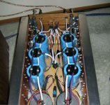
Well just to fill someone's possible interest ... I am using the 2sk109 as "blues buffer" for the zen V9 . It seems to work very good to me .
But I dont understand the schematic where there is a cascode for the jfet as buffer. Since it is working as a follower and its drain is already at ground and the input is at virtual ground cascode should not have any effect . Or the jfet should not gain anything from the cascode operation...
But I dont understand the schematic where there is a cascode for the jfet as buffer. Since it is working as a follower and its drain is already at ground and the input is at virtual ground cascode should not have any effect . Or the jfet should not gain anything from the cascode operation...
Hi Stefano,
I added the cascode to keep the "fragile" almost extinct jFET happily running along with a fairly constant Vds. They're a gift from Steenoe. The gate of the jfet also now sees about 12Vdc constantly from the feedback. Subjectively if there's any difference I don't know as I didn't try without cascode. From what I've read cascoding also lowers gate capacitance so that reduces another variable. Do you see a disadvantage though? BTW, I hate to throw away the 3310
allan
- Status
- This old topic is closed. If you want to reopen this topic, contact a moderator using the "Report Post" button.
- Home
- Amplifiers
- Pass Labs
- Buffer For Blues