Found a correction on Q4C cascoding mosfet...should be zvp3310.
Peranders, as you suggested I inserted a 1M resistor at the input like the F2 circuit.
Steenoe, I e-mailed Ruach my interest on the 2SJ74s but has not replied since.
Lineup, corrected circuit is in zip file again. I used to be able to convert a Word file into PDF but now can't.
Thanks guys!
Allan
Peranders, as you suggested I inserted a 1M resistor at the input like the F2 circuit.
Steenoe, I e-mailed Ruach my interest on the 2SJ74s but has not replied since.
Lineup, corrected circuit is in zip file again. I used to be able to convert a Word file into PDF but now can't.
Thanks guys!
Allan
Attachments
So you dont have any on hand??Steenoe, I e-mailed Ruach my interest on the 2SJ74s but has not replied since.
Send me an email with your adress and I will return a few of those darn sj74's

Steen
charging capacitor at input vs. input impedance
For charging a cap to 63% of the voltage
Time = R x C ; seconds
It is known that TIME CONSTANT
for
1M x 1uF = 1 sec
So go for 1M, if you have 1 sec to spare.
If you often are in hurry to get other things done in your life
you can save some time ( but you save less than 1 sec )
using 10 kohm or 100 kohm
But you should be aware, that resistor will DECREASE IMPEDANCE of input.
Making it a More Heavy Difficult Load, for example for Tube Amplifiers.
Say you design an amplifier with 470kohm input impedance.
Because you want it high.
Adding one 100kohm charging cap makes input impedance 82kohm ,,,,,
So much for your high input Z amp.
Rule of the thumb, could be:
Use charging cap >= 5 x input resistor, preferable x10
this will only sink the Z-in with ~20% resp. ~10%
For 470kohm input, we could use 2M2 or 4M7 charging resistor.
This is why I should go for 1 Mohm every time I need such charging cap,
may be at input or output of amplifier.
Because I can spare a couple of seconds, for sure.
Even if I now have less than 50% of my lifetime left ( past the 50! ).
About schematic.
I don't find there is any need to add such 1 Mohm resistance.
At least I wont make another image copy.
Because 9 times out of 10, we do not need that resistor anyway.
Because we have attached some source, before we POWER ON.
Regards
lineup
peranders said:Nelson, I would have a pulldown resistor at the input just to avoid accidental charging of the input cap. Resisitor value 100k-1M
.
For charging a cap to 63% of the voltage
Time = R x C ; seconds
It is known that TIME CONSTANT
for
1M x 1uF = 1 sec
So go for 1M, if you have 1 sec to spare.
If you often are in hurry to get other things done in your life
you can save some time ( but you save less than 1 sec )
using 10 kohm or 100 kohm
But you should be aware, that resistor will DECREASE IMPEDANCE of input.
Making it a More Heavy Difficult Load, for example for Tube Amplifiers.
Say you design an amplifier with 470kohm input impedance.
Because you want it high.
Adding one 100kohm charging cap makes input impedance 82kohm ,,,,,
So much for your high input Z amp.
Rule of the thumb, could be:
Use charging cap >= 5 x input resistor, preferable x10
this will only sink the Z-in with ~20% resp. ~10%
For 470kohm input, we could use 2M2 or 4M7 charging resistor.
This is why I should go for 1 Mohm every time I need such charging cap,
may be at input or output of amplifier.
Because I can spare a couple of seconds, for sure.
Even if I now have less than 50% of my lifetime left ( past the 50! ).
About schematic.
I don't find there is any need to add such 1 Mohm resistance.
At least I wont make another image copy.
Because 9 times out of 10, we do not need that resistor anyway.
Because we have attached some source, before we POWER ON.
Regards
lineup
Problem with input-buffer (ZenV4)
Hi!
I have got a small problem with my amps: Zen V4, PCBs bought at Passlabs.
The Mosfet that is suggested for the input of the Zen-V4, the ZVP3310, is hard to obtain here in Germany. As I read in this forum the BS250 should work fine. Well, it does not on my boards.
The voltage across Q4 is supposed to be about 4 V, with the BS250 it is just 0.66 V. Lowering the value of R13 does not really help rising the voltage-drop across Q4 as the effect is just... minimal.
With a negative offset at the input, the BS250 works. Without the offset.. well, I will show the pics as soon as I get them.
All the other voltages seem to be fine.
So now it looks like I would have to fiddle with the input-buffer, which (hopefully) gives me a great opportunity: Since I do not want to build a pre-amp with tubes or fets or anything but a simple box with a potentiometer, I would like the "input-buffer" to replace the preamp, i.e. to have some gain.
The questions:
- Is it the BS250 itself that is causing the problems or is there something wrong with my circuit? If I can get the input-buffer to work and the amps can play loud enough without a preamp, the questions below may become obsolete.
- Can this "buffer for blues" replace the preamp?
- What else could I build to raise the voltage?
peranders said:lineup, I'm not sure you understood me right. It's good not to have a capacitor with loose ends but this is only when you connect the amp with the power on. Otherwise it doesn't matter.
I know very well you know all about this, peranders.
Practically all there is to know .....
I just added a more detailed story onto your note.
For all other that WILL read this, this month and next month
and maybe after google search in 10 years from now
As there are all levels of knowledge and not knowledge
and misunderstandings and understanding,
I adjust my long long posts to lowest beginner level, mostly.
Long posts, in compare to Nelson Pass and peranders postings
- which often not say more than is needed, for the moment and serves as a good comment or reply.
As you say.
Using a charging resistor for input capacitor,
depends on situation, how you use your audio system.
Some have a static, even hardwired, soldered system chain.
Some use RCA phono for easy and flexible changes.
Some frequently switch between different setups,
sources, power amps and loudspeakers.
And whatever way you have it,
if you know what you are doing and you are the only to master your sound system ( I live alone )
nothing really bad can happen.
And here my small tutorials, like stories, comes in
- to make people aware,
to get to know more what effects this and that have or can have.
It is a lot different when living in family with several members, wife children
who also use same sound system and maybe re-arrange components.
Then can be very wise to play it safe - for 'worst case user'!
And use a resistor, in this case, for avoiding unpleasant sound sensations and surprises!
Regards
lineup
Luda, I dont think the stock z4 will work without preamp - at least mine does not.... I dont know if it adds gain, but ots called a buffer, and normally buffers just lowers the output impedance, and dont add gain...
My Z4 is at its best with a bosoz @20dB gain.....
Mabye you can change some values to get more gain from the 3310/250, mabye someone in here can help you??
Cheers !
Hans
My Z4 is at its best with a bosoz @20dB gain.....
Mabye you can change some values to get more gain from the 3310/250, mabye someone in here can help you??
Cheers !
Hans
Hi
I was wondering if ZEN V8 or V9 will see any benefit by using the P Ch Jfet buffer? My main concern is ZEN V8 without feedback. Even if there was some benefit, there are two things which I don't like.
1. Input capacitors. ZEN V8 is not using any input coupling cap. By adding a buffer we would have to use two caps. (one at the output of the buffer-10 uF perhaps), and 1 uF one at the input.
2. It seems that feedback resistor is playing a role at biasing the input buffer. If there was no feedback, then there should be other way to bias it?
Sorry for dumb questions.
thanks,
Vix
Vix said:I was wondering if ZEN V8 or V9 will see any benefit by using the P Ch Jfet buffer?
I understand that the main purpose of the buffer is
to increase the input impedance
ZV8 has a high input impedance with the buffer, Q1
ZV9 (with negative feedback) has a relatively lower value


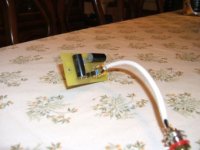
Here are preliminary pictures of the Blues Buffer (B^2)boards I made. These will ride piggy back on a Zenv4 pcb to replace the mosfet input buffer circuit with a jfet. The circuit board can also be used as a BB Brother (B^3) board which has a cascode circuit using a mosfet...in this case the zvp3310.
Attachments
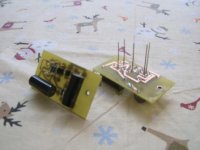
Jfets are 2SJ74s through the kind heart of Steen all the way from Singapore via the beautiful Kenteminde.
In Holiday tradition, note that I strung together yellow Christmas lights to get about 1.6pF for the feedback cap...due to not having an oscilloscope I'm relying on the Sim software to give me a nice square wave at 10kHz onwards.
Will post pics with the Zv4 board as soon as I receive the 3W 2kR21 bias resistor which I ordered initially at 1/4W. Darn! It's a wait until after Christmas.
Attachments
Thats a nice little project. I am looking forward to hear about your listening impressions. Pretty exciting to see if the J-fet buffer has the same influence on the sound as the J-fet diff pair has in an AlephHere are preliminary pictures of the Blues Buffer (B^2)boards I made.
Steen
One Channel Up
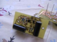
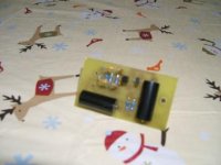
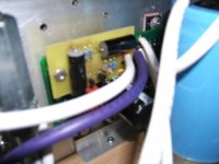
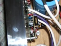
Singing in mono the jfet buffer is indeed sweet. The sound is now more extended in the high frequencies, midrange is still as sweet as can be. The bass sounds promising and can be more appreciated in stereo (still working on the left channel). In mono the music is now more defined and clearer compared to the old buffer. With a stock Aleph 3 as my reference the Zenv4 used to lag in this department and in the high frequencies. It has changed and I like what I hear. More on the sound when I get it in stereo.
Here are pictures of the working channel. Big grin indeed!
Singing in mono the jfet buffer is indeed sweet. The sound is now more extended in the high frequencies, midrange is still as sweet as can be. The bass sounds promising and can be more appreciated in stereo (still working on the left channel). In mono the music is now more defined and clearer compared to the old buffer. With a stock Aleph 3 as my reference the Zenv4 used to lag in this department and in the high frequencies. It has changed and I like what I hear. More on the sound when I get it in stereo.
Here are pictures of the working channel.
Big grin indeed!Attachments
- Status
- This old topic is closed. If you want to reopen this topic, contact a moderator using the "Report Post" button.
- Home
- Amplifiers
- Pass Labs
- Buffer For Blues