I have a breadboard opamp headphone amp I built a couple years ago I have been using that I would like to upgrade. I am a night owl so I like to listen to music or watch movies late at night and not annoy people sleeping. I really want tubes but can't spend much money on this project. Being that the iron is going to be the expense I was looking into using some 70v line matching transformers that I have on hand for the output stage in a push pull configuration. I do not need this to be "hi-fi", just functional (but with some reasonable bandwidth). I have a regulated B+ supply of up to 400V, one transformer that I would like to use for a project would only yield me 200V B+, but if the results will suffer I will use the 330-0-330.
I have soo many 12AU7's laying around I think I would like to use them up for something.
Brimar states that a very satisfactory class A1 push pull amp of up to 1200mW can be achieved http://frank.pocnet.net/sheets/184/1/12AU7.pdf I noticed that for a Va of 300V they used an anode load of 10k, and for Va of 250 they used 15k. Is this plate to plate? I figure the 32x tap on the line transformer would be 32k plate to plate driving my headphones. I am thinking the 15k anode load isn't plate to plate and that the 32x tap should work out perfectly. Looks like I will have to draw up some load lines.
Somebody please stop me with this if I am wasting my time using the line matching transformers. I am thinking it can be a fun project to use up some stuff I got laying around. Hopefully I will be able to propose a schematic here soon for you guys to look over for me, until then happy holidays
Depending on your headphone impedance, you might even be able to go output transformerless. Search for white cathode follower headphone amp and 6as7 otl headphone amp. The first should give reasonable power to 32ohms while the latter is better suited for 300ohms. Later if you find distortion is too high, you can always put the output transformer in.
What phones do you have?
Hi MrCurwen,
I have the Sennheiser HD449.
Perhaps you could use the transfomers single ended.
Hi Sreten, nothing is carved in stone as of yet, I am fishing for ideas which led me to starting a thread. Thanks for your suggestion, I have thought of going single ended but didn't want the DC current to saturate the core.
Depending on your headphone impedance, you might even be able to go output transformerless. Search for white cathode follower headphone amp and 6as7 otl headphone amp. The first should give reasonable power to 32ohms while the latter is better suited for 300ohms. Later if you find distortion is too high, you can always put the output transformer in.
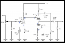
Hi Ballpencil, I found the schematic I attached, is this one design you are suggesting? As stated above, nothing is set in stone so thanks for the suggestions I will consider all
")
Attachments
I found a good explanation on Tubecad Tube CAD Journal: Tube regulators part 2, July 1999
The math is a little tougher than a cathode follower to determine the Zout LOL BUT wow can you get a low Zout Thanks! This is why I asked for suggestions
The math is a little tougher than a cathode follower to determine the Zout LOL
BUT wow can you get a low Zout Thanks! This is why I asked for suggestionsIt would help to know exactly what you have on hand as 70V line transformers. Usually, they need to be driven from a low impedance to have a satisfactory frequency response.
These are the ones I have: 70V 10W Line Matching Transformer
An OTL with 12AU7 won't really cut it with 32R headphones.
Yes I see, I need to look around for a high transconductance tube, something like the 6DJ8. I have a big box of TV tubes I will sort through.
12AU7 Zout 1/.00312 = 320
It's strange, or maybe it's too late for me to do math but when I was looking into the white cathode follower I kept getting a higher output impedance than a standard cathode follower.
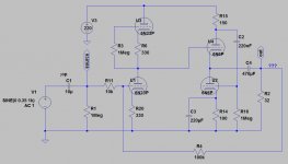
Must you use 12AU7 all around? I mean, Russian 6N6P is very cheap and it would make an excellent White Cathode Follower output tube. You can use the 12AU7 for the gain stage.
Attached is the result of me fiddling on LTSpice for 32 ohm load WCF. I can reach 2.4Vpp to 32 ohm load at 1.2% THD. I believe you'd lost permanent hearing at that level.
Attached is the result of me fiddling on LTSpice for 32 ohm load WCF. I can reach 2.4Vpp to 32 ohm load at 1.2% THD. I believe you'd lost permanent hearing at that level.
Attachments
Must you use 12AU7 all around? I mean, Russian 6N6P is very cheap and it would make an excellent White Cathode Follower output tube.
No, I don't have to use the 12AU7. I just asked myself what are the most expensive parts in most tube amps.....and figured it is transformers and tubes. So i started with what tubes I had and remembered a note about the 12AU7 used as a pp output stage. Eliminating the output transformers would be ideal and I did notice in here: http://www.jj-electronic.sk/pdf/ECC99.pdf headphone amp is under recommended uses. Great idea! Thanks.
I know I can't probably use everything in my spare parts boxes but I sure can try
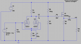
I try to recycle and or use what's at my disposal on some projects.Well I canned a tube output stage........I think I will go with a source follower to drive the headphones. I attached some files if anybody would like to look over the design and give some feedback. I am going to use a IRF830 at about 44 watts of dissipation. I plan to use the 12AU7 heater filaments in series as the source resistor. I estimated them to be 84 ohms in series. Is this too much? I have some heatsinks that I need to dig out, I will post pictures if somebody could tell me if they will be adequate for the Mosfets. I pretty much have everything on hand for this except the Mosfets so it should be a pretty cheap experiment. Happy Holidays to all
Attachments
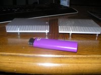
44W dissipation just for a headphone amp? Anyway, those heatsinks don't look up to the task for 44W. Here's an alternative for you:
SSMH Variations It uses the heaters as source load as you planned. Much lower (safer) voltage as well.
SSMH Variations It uses the heaters as source load as you planned. Much lower (safer) voltage as well.
44W dissipation just for a headphone amp? Anyway, those heatsinks don't look up to the task for 44W. Here's an alternative for you:
SSMH Variations It uses the heaters as source load as you planned. Much lower (safer) voltage as well.
That is pretty much exactly what I had in mind. I guess 5 watt through the Mosfet is a little better
 The heatsinks should be adequate for that.
Well I canned a tube output stage........I think I will go with a source follower to drive the headphones. I attached some files if anybody would like to look over the design and give some feedback. I am going to use a IRF830 at about 44 watts of dissipation. I plan to use the 12AU7 heater filaments in series as the source resistor. I estimated them to be 84 ohms in series. Is this too much? I have some heatsinks that I need to dig out, I will post pictures if somebody could tell me if they will be adequate for the Mosfets. I pretty much have everything on hand for this except the Mosfets so it should be a pretty cheap experiment. Happy Holidays to all
Have you seen these?
DIY 12AU7 Tube Preamplifier Project
Starving Student hybrid
NP-100v12: DIY 12AU7 (ECC82) Tube / IRF510 MOSFET Headphone Amplifier
Check out my headphones amp design. For low cost you can use a couple of Edcor transformers at about $12 each:
http://www.diyaudio.com/forums/tubes-valves/191632-improved-tube-headphones-amp.html
Cheers
Ian
http://www.diyaudio.com/forums/tubes-valves/191632-improved-tube-headphones-amp.html
Cheers
Ian
Second the Twilight amp.
I would replace R5 with a CCS (set to 5...10mA) to get maximum fidelity (lowest possible output impedance), and replace R6 with an OT (10k : 4 ohm), since I've found low impedance driven parafeed OTs to be much more transparent than big electrolytic caps.
That would be the best SE output topology.
I would replace R5 with a CCS (set to 5...10mA) to get maximum fidelity (lowest possible output impedance), and replace R6 with an OT (10k : 4 ohm), since I've found low impedance driven parafeed OTs to be much more transparent than big electrolytic caps.
That would be the best SE output topology.
- Status
- This old topic is closed. If you want to reopen this topic, contact a moderator using the "Report Post" button.
- Home
- Amplifiers
- Tubes / Valves
- "budget" headphone amp