Use the 12AU7 with both triodes in parallel in place of the 6CG7 or 6SN7 since you wanted to use 12AU7s to begin with.
Use a 1K cathode resistor for the two triodes in parallel.
Although with a 60V B+, it is not going to be very linear no matter what you do. You need 20V for the top FET, leaving you with only 40V across the tube.
If you are going to use the Mu-follower topology, increase the B+ to get better performance from it.
Single ended it will be mostly 2H, for his original objective I believe it could be made linear enough to be quite satisfactory.
Question for the OP is do you want build something with the tubes you have or go off in another direction.
The 12AU7 was his original request so lets optimize the circuit as best we can and let him breadboard it to see if it is good enough.
Question for the OP is do you want build something with the tubes you have or go off in another direction.
The 12AU7 was his original request so lets optimize the circuit as best we can and let him breadboard it to see if it is good enough.
I really like Pete's "Starving Student" design
Check out my headphones amp design. For low cost you can use a couple of Edcor transformers at about $12 each:
http://www.diyaudio.com/forums/tubes-valves/191632-improved-tube-headphones-amp.html
Thanks, I will read through the whole thread BUT I really can't put any $$ into this. This isn't a big project so waiting around for the iron isn't what I want to do even if I had the extra money, Edcor takes 8 weeks to fill the order usually.
If you have several 12AU7s, why not parallel sections for lower output impedance?
In a cathode follower configuration?
Or, you could try to adapt RJM's Twilight tube-MOSFET hybrid mu follower to your needs.
This design seems to be ill suited for my needs. The output impedance is dependent on the Transconductance of the Mosfet, with the 2SK213 in the Twilight it's 10 ohms.........not that great with only 10mW into a 32 ohm load. The variation of the "Starving Student" amp I presented is a little less than 3 ohms out.
Second the Twilight amp.
I would replace R5 with a CCS (set to 5...10mA) to get maximum fidelity (lowest possible output impedance), and replace R6 with an OT (10k : 4 ohm), since I've found low impedance driven parafeed OTs to be much more transparent than big electrolytic caps.
That would be the best SE output topology.
I am really not going for "best" topology on this project, maybe in the future I can go all out. This project is all about getting the drive capability for the cans with decent distortion figures with the parts I have on hand. I am happy w/ anything <1% THD and a minimal 3ohm output impedance. Bandwidth is important too of course
")
Single ended it will be mostly 2H, for his original objective I believe it could be made linear enough to be quite satisfactory.
Question for the OP is do you want build something with the tubes you have or go off in another direction.
The 12AU7 was his original request so lets optimize the circuit as best we can and let him breadboard it to see if it is good enough.
I do want to use the tubes I have on hand. As stated this is a fun project and I won't be optimizing circuits with CCS' or anything, resistive loads will be adequate as well as lytics' in the signal path (which I am usually not fond of). This reminds me, my friend wants me to recap his Mcintosh C2200. I will most likely start another thread on the subject but oh man are there a lot of lytics' and opamps in the signal path.
OK, lets define what you want to make (the scope of the project).
You have a set of headphones with 32 Ohm impedance (nominal) and a sensitivity of 114dB (per what? 1Vrms most likely but the mfg web site is not specific.
You want <1% THD, at what output level? 1Vrms which will give you 114dB spl?
You want an output impedance of 3 Ohms or less.
You prefer to use 12AU7s as a gain stage, which is going to be 10-12 AV depending on the topology (less than 1 in a cathode follower).
Anything I've missed?
1V rms into 32 ohms is 31.25mA rms or just over 44mA peak. If you are going to do this without transformers or semiconductors you need some sort of push pull stage running at a quiescent current of over 20mA. You could run a pair of 12AU7s in an SRPP at about 12.5mA each for a total quiescent of 25mA. A 12AU7 in an SRPP topology will produce a lot of distortion so you will need some NFB. If you want to stick with the 12AU7 you could one as a preamp/driver stage set up as a cascode to get a reasonable amount of gain. dc NFB from the SRPP to the cascode cathode should ensure stability.
Edit: As there is no OP transformer you need approximately unity gain overall so you probably do not need the cascode first stage and could probably get away with a regular common cathode first stage.
Just a thought.
Cheers
Ian
Edit: As there is no OP transformer you need approximately unity gain overall so you probably do not need the cascode first stage and could probably get away with a regular common cathode first stage.
Just a thought.
Cheers
Ian
Last edited:
Anything I've missed?
Just bandwidth, I would like as close to 20-20kHz as possible. Other than that you got the criteria.
I have a lot of common value caps and resistors. A bunch of 12AU7's and a bunch of 6SN7's. Some heatsinks, a regulated power supply capable of up to 400v. I have a 100VA, 40Vct or 80Vct power transformer depending on how I wire the primary. And the 70v line transformers I was asking about initially. Two octal sockets, 3 noval sockets, random RCA jacks and a few switches. I even have a a couple power cables lying around. The chassis isn't decided but it will be home made.
1V rms into 32 ohms is 31.25mA rms or just over 44mA peak. If you are going to do this without transformers or semiconductors you need some sort of push pull stage running at a quiescent current of over 20mA. You could run a pair of 12AU7s in an SRPP at about 12.5mA each for a total quiescent of 25mA. A 12AU7 in an SRPP topology will produce a lot of distortion so you will need some NFB. If you want to stick with the 12AU7 you could one as a preamp/driver stage set up as a cascode to get a reasonable amount of gain. dc NFB from the SRPP to the cascode cathode should ensure stability.
Edit: As there is no OP transformer you need approximately unity gain overall so you probably do not need the cascode first stage and could probably get away with a regular common cathode first stage.
Just a thought.
Cheers
Ian
I will draw up some different topologies including an SRPP before I set anything in stone. The SRPP will likely have an output impedance of around 3k using a 12AU7, not good enough, maybe with feedback it will be lowered but I doubt I will get below 3 ohms without an OP transformer. Besides, looking at Pete Millets SRPP headphone amp using Sowter output transformers and B+ of 300, the Starving student amp gets lower distortion figures with a B+ of 48V
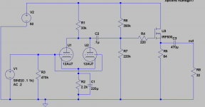
This is why I am leaning towards the Starving Student design. Here is the revised edition of what I have so far. I only have some IRF830's on hand so I modeled them. *Note: The 84R source resistor is the series 12AU7 heater elements.
Attachments
Last edited:
I will draw up some different topologies including an SRPP before I set anything in stone. The SRPP will likely have an output impedance of around 3k using a 12AU7, not good enough, maybe with feedback it will be lowered but I doubt I will get below 3 ohms without an OP transformer. Besides, looking at Pete Millets SRPP headphone amp using Sowter output transformers and B+ of 300, the Starving student amp gets lower distortion figures with a B+ of 48V
Here is the revised edition of what I have so far. I only have some IRF830's on hand so I modeled them. *Note: The 84R source resistor is the series 12AU7 heater elements.
My 'Improved Tube Headphones Amp' is the Pete Millet design with NFB. From the cicuit you posted it would appear that the starving student gets lower distortion figures simply because it has a semiconducotr output stage.
I am not clear why you think an output impedance of 3 ohms is required. Can you elaborate?
Cheers
Ian
I am not clear why you think an output impedance of 3 ohms is required. Can you elaborate?
Proper bass response.
Just throwing my name in the hat here. My Novar Spud would be perfect for a headphone driver. You could build it with 5k:8Ω OPTs and have outputs both for speakers and headphones (via a matching network).
Novar Spud: 6LR8, 6KY8, or 6GF7A one-tube amplifier.
~Tom
Novar Spud: 6LR8, 6KY8, or 6GF7A one-tube amplifier.
~Tom
1V rms into 32 ohms is 31.25mA rms or just over 44mA peak. If you are going to do this without transformers or semiconductors you need some sort of push pull stage running at a quiescent current of over 20mA. You could run a pair of 12AU7s in an SRPP at about 12.5mA each for a total quiescent of 25mA. A 12AU7 in an SRPP topology will produce a lot of distortion so you will need some NFB. If you want to stick with the 12AU7 you could one as a preamp/driver stage set up as a cascode to get a reasonable amount of gain. dc NFB from the SRPP to the cascode cathode should ensure stability.
Edit: As there is no OP transformer you need approximately unity gain overall so you probably do not need the cascode first stage and could probably get away with a regular common cathode first stage.
Just a thought.
Cheers
Ian
I simulated this the other night. The output R is indeed close to 3K because with a 32 ohm load the output drops by 20dB. The distortion is around 10% at one volt rms output which is par for the course for the 12AU7. With a CC first stage the overall gain is close to unity so there's not enough open loop gain to add NFB. To make it work would probably need the cascode first stage but even with 20dB of NFB the distortion would still be around 1%. You really need a valve with a lower anode resistance.
Cheers
Ian
Proper bass response.
Not sure why you think a 3 ohm output impedance is required for that. Standards recommend driving headphones from a voltage source via 120 ohms and this does not cause bass response problems.
Cheers
Ian
Not sure why you think a 3 ohm output impedance is required for that. Standards recommend driving headphones from a voltage source via 120 ohms and this does not cause bass response problems.
120 ohms into 32 ohms is no longer a voltage source, more like a current source. The load of the headphones is dependent on frequencies, the lower frequencies are most likely less than 32 ohms. With a voltage source the bass would be tighter due to a better dampening factor, and more enhanced due to higher power out (pure voltage source would double power when the load is halved). With a high output Z the opposite happens, as the headphone impedance drops with frequency so does the power output giving the effect of lacking bass.
I don't have much experience with headphones but the 120R standard sounds like it is an old standard back when headphone impedance was anywhere from 300 to 2k.
I don't have much experience with headphones but the 120R standard sounds like it is an old standard back when headphone impedance was anywhere from 300 to 2k.
IEC 61938
Cheers
Ian
Having tried different things out, I've found that my nominally 120 ohm AKG601s do best - by a very large margin - when driven by a low impedance source.
I use a 10k : 4 ohm transformer, and the primary is driven by a low impedance source (somewhere in the tens of ohms, I should figure this out precisely).
Based on my experiences, I would absolutely not recommend driving headphones thru a 120 ohm resistor, no way.
I use a 10k : 4 ohm transformer, and the primary is driven by a low impedance source (somewhere in the tens of ohms, I should figure this out precisely).
Based on my experiences, I would absolutely not recommend driving headphones thru a 120 ohm resistor, no way.
Based on my experiences, I would absolutely not recommend driving headphones thru a 120 ohm resistor, no way.
I agree, whether "they" say it's a standard or not, and or the headphones are high Z type.
Your design w/ the 10K : 4 transformer sees 300k with those AKG601's, that's an easy load to drive
Unfortunately I am not springing for iron on this project and will probably use sand for the finals. I was tempted to go the Edcor route utilizing my 6SN7's as a white cathode follower, but I don't feel like waiting 2 months. If I push enough current, say 20mA through a 6SN7 cathode follower would it be enough to drive the C of the line transformers? I remember reading somewhere on here that there is a rather large capacitance for line transformers and you need enough current to get a good slew rate.
I lack the tools to measure the properties of a line transformer, has anybody on here made a model for Spice on here for one? Do models even have the capacitance in them? The ones I use seem to just have resistance and inductance
I suppose it might be easier to just wire one up and take some measurements and do some listening tests. But designing on paper and simulating first is half the fun
IEC 61938
About the only manufacturer to still adhere to that standard for some headphones is Beyerdynamic (if they actually still do.. I didn't check recently). All other manufacturers design their headphones for near 0 ohms output impedance and have stated so. When they produce headphones amplifiers (grado, sennheiser,..), they certainly do have a low output impedance.
Obviously, as the main impact of output impedance is due to the interaction in between the amp's output impedance and the impedance vs frequency characteristic of the headphones, it could or not be important. Some headphones with very flat impedance vs frequency won't care much, some with more tormented curves will.
Having tried different things out, I've found that my nominally 120 ohm AKG601s do best - by a very large margin - when driven by a low impedance source.
I use a 10k : 4 ohm transformer, and the primary is driven by a low impedance source (somewhere in the tens of ohms, I should figure this out precisely)..
I do not understand this. if your source imedance is 'somewhere in the tens of ohms' why do you need a transformer with a 2500:1 impedance ratio to drive a 30 ohm load?
Cheers
Ian
- Status
- This old topic is closed. If you want to reopen this topic, contact a moderator using the "Report Post" button.
- Home
- Amplifiers
- Tubes / Valves
- "budget" headphone amp