Dear,
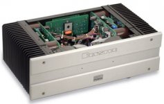
I don't have high resolution pic's but this is everything I can find. Hope it helps!
The elco's are 105 degrees types, and the amp really remain cool inside all time with moderate listening level's
Kind regards,
Bas
I don't have high resolution pic's but this is everything I can find. Hope it helps!
The elco's are 105 degrees types, and the amp really remain cool inside all time with moderate listening level's
An externally hosted image should be here but it was not working when we last tested it.
An externally hosted image should be here but it was not working when we last tested it.
An externally hosted image should be here but it was not working when we last tested it.
Kind regards,
Bas
pinkmouse said:Yes, I must admit, looking at those boards in comparison to the schematics, they do seem slightly oversize for what they could be.
Does that mean potential for improvements over the original regarding sound through a more compact PCB design with shorter paths?
If so:

chicco_36 said:I’m for main capacitors on board. From all reviews that I read, 3BSST runs cool so heat wouldn’t we an issue.
Chicco
That's not the real issue though. The 3 large PCB's required for a stereo amp would be expensive. We need to cut the size down otherwise nobody will be interested in a groupbuy that costs $50-60 just for the PCB's and that's IF we get a decent number of people interested and a decent number of boards ordered.
Look at the KSA group buy - $28 for a stereo amp.
Not only that but there's potential in the layout that could even improve performance. Al did the KSA very well and some even report that it sounds better than their original KSA50's.
Let the guy do his thing and see what he comes up with
I still dislike the caps on the main board and heat generation has nothing to do with it... fine for a production unit but no good for a DIY unit where most here would be much more likely to add alot more capacitance than what the factory included... which in alot of cases is the bare minimum..... This would also drive up the board cost alot due to size and would not allow for power supply traces to be heavier than the amp traces which they should really be. Are we building a better amp or just a duplicate of the factory amp....? If we are building a better amp count me in but if not see ya around....
Mark
Mark
Mark A. Gulbrandsen said:I still dislike the caps on the main board and heat generation has nothing to do with it... fine for a production unit but no good for a DIY unit where most here would be much more likely to add alot more capacitance than what the factory included... which in alot of cases is the bare minimum..... This would also drive up the board cost alot due to size and would not allow for power supply traces to be heavier than the amp traces which they should really be. Are we building a better amp or just a duplicate of the factory amp....? If we are building a better amp count me in but if not see ya around....
Mark
My sentiments exactely Mark.
DIY is about exploring and I think we'd be missing the point if we tried to do a straight copy.
need parts
http://cgi.ebay.ca/STEREO-4B-ST-BRY...815519712QQcategoryZ50593QQrdZ1QQcmdZViewItem
dead channel hmm this guys good fast delivery
http://cgi.ebay.ca/STEREO-4B-ST-BRY...815519712QQcategoryZ50593QQrdZ1QQcmdZViewItem
dead channel hmm this guys good fast delivery
Hi Al,
I think this is worth doing right, not just a copy. Why would you just copy this thing? ShinOBIWAN is right on that point.
So it takes some time, I believe we can do a much better job. Starting with the power supply filtering / snubbing. Possibly shielding it from the signal path.
-Chris
I think this is worth doing right, not just a copy. Why would you just copy this thing? ShinOBIWAN is right on that point.
So it takes some time, I believe we can do a much better job. Starting with the power supply filtering / snubbing. Possibly shielding it from the signal path.
-Chris
I think one board for 1 channel with main capacitors, or place for them, another one optional for discrete op-amps (not my cup of tea), and third, which not need pcb, external PSU. If we go that way, we well and up with two main boards for stereo amp and possibilities for upgrading.
All of you, please look at the schematic, when you exclude op-amps and psu, the main board (schematic) is relatively speaking very simple. If we complicate things, no one will like to build it. Or no one will like to pay for 4 or 6 boards if we go for group buy.
Chicco
All of you, please look at the schematic, when you exclude op-amps and psu, the main board (schematic) is relatively speaking very simple. If we complicate things, no one will like to build it. Or no one will like to pay for 4 or 6 boards if we go for group buy.
Chicco
I thought the whole point of having the power supply caps on the main board was to keep the PSU output impedance to a minimum. McCormack does it that way and calls it DNA, which is kind of overboard, but I believe it was Jocko Homo who really approved of the practice. Having a separate PSU board is fine, but I'd still like a sizable portion of the capacitance on the main board, however much it adds to the price. BTW, in an age of GainKlones, what exactly is the optimum capacitance anyway? Does more capacitance always give you better performance?Mark A. Gulbrandsen said:I still dislike the caps on the main board and heat generation has nothing to do with it... fine for a production unit but no good for a DIY unit where most here would be much more likely to add alot more capacitance than what the factory included... which in alot of cases is the bare minimum..... This would also drive up the board cost alot due to size and would not allow for power supply traces to be heavier than the amp traces which they should really be.
We also seem to have done away with the so-called "op-amp" input stage/bridge circuitry, but is this something everyone wants to do? If no one wants it that's fine, but my 3B-ST sure had a lot more bounce when used balanced-bridged... While I wouldn't call the sound neutral (too full bodied and syrupy), it sure as heck was a lot more fun to listen to. I personally wouldn't mind seeing an option for a board like this.
Another thing that might have been mentioned was that the input board places the high impedance input node of the amplifier right at the input connectors of the amplifiers, which is really where it should be. The main board is driven by the input board with a known, low, O/P impedance. Not necessarily the case with all pre-amps out there... This can be solved by clever board design, like in the Aleph 30, but most group buy boards I've seen haven't been designed to mount close to the input connectors. This is something that's going to have to be addressed if you're planning on approaching the performance of the original 3B-SST.
I'm not saying it can't be done, I believe it will be very difficult to surpass the performance of the 3B-SST. I think Bryston has put a lot of thought into the design of their amplifiers, which of course includes board layout, but also encompasses, wiring, chassis grounding, and parts/board placement. That they've gone out of thier way to create an amplifier with such a complicated assembly, seems to suggest that not everything was done to keep production costs to a minimum. As you approach ever decreasing amounts of distortion, a key feature of Bryston amplifiers, even very small details play a part in maintaining that performance. If we are going to create an amplifier that betters the performance of an SST, I think we're going to have to look at more than just the PCB.
None of this meant to deter anyone's efforts. It's actually the opposite because I really do want to see this a project like this succeed. It's just that everyone seems to think it's going to be easy to surpass the SST just because it's a DIY effort. With an amplifier like this, it might just be the opposite. Manufacturers spend a lot of time creating multiple revisions to finally create someting that works well. For example I heard Stuart Taylor spent a lot of time hunting down miniscule ground loops to get this thing where it is. I'm really not qualified to say, but what do some of the experts on this board say? Is this project to create a better sounding version of the SST really feasible?
Hi greyhorse,
A commercial amp will always be compromised by cost in some way. We have a pool of talent that exceeds most closed companies. It's good to remember too, there is nothing you can do that others can't do, possibly better. Mind that it may take a while.
I'd like to keep really high charging current pulses off the amp boards. You don't need a big cap to supply peak demands with a capacitor bank nearby. Feed the audio circuits with a spikeless DC. This will also give some flexibility to the design.
If the filter caps are constructed on a separate PCB, it will not be difficult to make. There are choices the constructor can make to reduce costs. or to exceed the basic design. Heck, that's what we do isn't it? I'm not very concerned about multiple PCB's.
-Chris
Ok, so we're starting to get somewhere.
With pcbs, the cost isn't so much based on board area as you might think. Number of layers, drills, silks, and masks all have an influence, but the biggest of all is quantity. We need to get people on board!
So, I'm thinking of a compromise situation. I would definately go for a main PSU board, simply because of the flexibility it allows, and like Chris, I like to keep charging spikes off the main boards. However, for those that want, I see no reason why we couldn't have "wings" on the main board for extra close-up capacitance. These could be scored for removal if not required, and if we think about the design properly, might even be of use in building something else. Waste not, want not!
- Status
- This old topic is closed. If you want to reopen this topic, contact a moderator using the "Report Post" button.
- Home
- Amplifiers
- Solid State
- Bryston 3B SST, enyone interested?