OK, learning this is really fun. Thanks.
I checked the continuity along the blue line and it is 0 volt.
I checked the voltage at IC301. Pin 8 (B+) and it is 15.50 volts.
Pin 4 (B-) reads 15.58 volts. I had the neg metere lead on pin 4 and the pos lead on the chassis as you said to do, but I didn't get a neg reading of -15.58 like the schematic says. I guess it would be a negative reading if I reversed the meter leads.
So far so good. What do you suggest next? Is it time to learn to about measuring rail voltage?
I agree with ilimzn. My guess (without listening to the unit) is that either the 'lytics have leaked (highly likely in any equipment of this vintage) or there is a ground issue somewhere. Electrolytic caps have a tendency to leak electrolyte with increasing age, thus losing their capacitance properties. Which is why it is a good idea to recap this unit even after/before you solve this particular issue, especially if you plan on keeping the unit.
Does this unit have a three-prong or two-prong plug? If three-prong, try a 3 to 2 prong adapter at the wall receptacle. If 2 prong, try reversing (flipping the prongs opposite to how they currently are at the wall) the plug at the wall receptacle. Also, you might want to try the amp at another wall receptacle. You would be surprised how "dirty" those ground circuits are in our walls. It sure sounds like a ground fault somewhere...
Does this unit have a three-prong or two-prong plug? If three-prong, try a 3 to 2 prong adapter at the wall receptacle. If 2 prong, try reversing (flipping the prongs opposite to how they currently are at the wall) the plug at the wall receptacle. Also, you might want to try the amp at another wall receptacle. You would be surprised how "dirty" those ground circuits are in our walls. It sure sounds like a ground fault somewhere...
OK, learning this is really fun. Thanks.
I checked the continuity along the blue line and it is 0 volt.
I checked the voltage at IC301. Pin 8 (B+) and it is 15.50 volts.
Pin 4 (B-) reads 15.58 volts. I had the neg metere lead on pin 4 and the pos lead on the chassis as you said to do, but I didn't get a neg reading of -15.58 like the schematic says. I guess it would be a negative reading if I reversed the meter leads.
So far so good. What do you suggest next? Is it time to learn to about measuring rail voltage?
Those readings sound OK. Yes, the voltage would be "negative" if the leads were reversed. We would normally keep the black meter lead on the chassis and say + 15 volts on pin 8 and - 15 volts on pin 4
The blue line is at zero volts. With the amp off can you confirm that the blue line also reads zero ohms (a short) to the outer (ground) part of all the input sockets.
Things get a bit more difficult after this because without a scope to see what is happening, we have to rig little tests up to try and deduce where the problem is.
I think I got confused when measuring continuity on your blue line. I revised my original test points because I think I measured the wrong side of C 319.
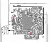
Here is a picture of the volume board from the manual. I circled what I think is now the correct test points. My new measurement fluctuates between 6 and 7 ohms. That is if I'm measuring the correct side of the capacitor.
When I measure from C319 to the input grounds I get 504 k ohms. And when I measure from C319 to direct input and preamp output ground fluctuates between 2 and 3 ohms.
Attachments
Last edited:
Those readings seem "OK" The middle pin of the volume control is actually the wiper but with the volume turned on minimum it should connect to ground, and from those readings it appears to be doing so.
You should be able to read a short circuit between any of the input sockets (CD/AUX etc) and C319.
I really don't know what to suggest to you. Ideally it needs a scope.
Without, and it needs you to be able to isolate the inputs to the power amps and tag in a suitable pot and test the power amps with a direct source such as a CD player. That would conclusively prove if the power amps were OK.
You must find that trace yourself... start from the middle pin of volume pot...
Or you can try pull out volume pot & inject the signal from the middle hole")
see what happen next
There two relays on board, are they clicking... I hope they're not broken, check it too
Or you can try pull out volume pot & inject the signal from the middle hole
see what happen next
There two relays on board, are they clicking... I hope they're not broken, check it too
Last edited:
The input is directly across C319. So the wiper of the pot goes to the top end of C319, the ground of the pot to the bottom of C319 and the CD player input directly to the "top" of the pot. The signal ground of the CD player goes to the pot ground. You would also disconnect the existing inputs to the power amp board so that it was using just the added new one.
If you try anything like this then I would advise connecting the speakers via a 100watt bulb initially in case anything was amiss in the wiring.
If you try anything like this then I would advise connecting the speakers via a 100watt bulb initially in case anything was amiss in the wiring.
Does this look like the correct place to try power amp in from a preamp or variable output source?
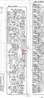
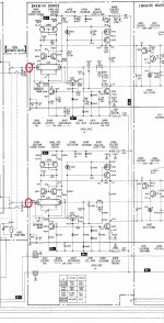
I circled on schematic and circuit board layout where I think the power amp in is located? Am I correct? Can I just unplug jumper and use jumpers to connect from variable source?
I circled on schematic and circuit board layout where I think the power amp in is located? Am I correct? Can I just unplug jumper and use jumpers to connect from variable source?
Attachments
Yes, you can separate the pre and power amps at that point. Be aware that the high gain of the power amp means that the replacement pot must be soldered in before powering up. Don't leave it floating. And use a bulb as I mentioned to protect the speakers and amp in case anything should go wrong.
(I'm wondering maybe that this might be a bit of an ambitious project for you to start with)
(I'm wondering maybe
that this might be a bit of an ambitious project for you to start with)I hate to be a bother everyone again. I feel like I'm a bother, but I have another observation. I unplugged the jumper that goes from the "Volume board' to the 'Power A board' so I could use just the power amp section.
What happened was that one of the red LEDs on the 'power A board' went out and the amp wouldn't come out of protection. I turned amp off and on and this time the other led went off and it wouldn't come out of protection. I plugged the jumper back on and now both red leds on the 'power A board' are lit as well as the two red leds on the 'Power B board' like from when I purchased this amp in its broken state.
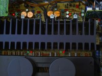
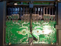
This is the way it was from the onset. I assumed that if the humming problem can be resolved that these four leds would turn off, or turn green. Here is a photo of them. The top board is 'power A board' and the bottom board below the heat sink is the 'power B board'. I put a green arrow pointing to them. What do you make of these LEDs?
What happened was that one of the red LEDs on the 'power A board' went out and the amp wouldn't come out of protection. I turned amp off and on and this time the other led went off and it wouldn't come out of protection. I plugged the jumper back on and now both red leds on the 'power A board' are lit as well as the two red leds on the 'Power B board' like from when I purchased this amp in its broken state.
This is the way it was from the onset. I assumed that if the humming problem can be resolved that these four leds would turn off, or turn green. Here is a photo of them. The top board is 'power A board' and the bottom board below the heat sink is the 'power B board'. I put a green arrow pointing to them. What do you make of these LEDs?
Attachments
Two leds are used as a cascode reference voltage drop (D418, D468), and two are used as a voltage drop in the bias circuit (D407, D457). Both should always be on. They are not used as indicators.
If they are going out, there is a problem. D418/468 going out would likely lead to the unit getting stuck in protection as without this voltage the VAS stage (formed by Q405/Q406 and Q455/Q456) will not work.
If they are going out, there is a problem. D418/468 going out would likely lead to the unit getting stuck in protection as without this voltage the VAS stage (formed by Q405/Q406 and Q455/Q456) will not work.
The audio comes into the power amp by the connector labelled EH15 on the "Main A board" - that's the topmost board in your picture with the 4 gold capacitors on it. That should be the only one you disconnect.
It doesnt help that the schematic diagram completely omits the inter-board connections.
It doesnt help that the schematic diagram completely omits the inter-board connections.
Jaycee,
I unplugged the connector that goes from the volume board to the EH15 input connector on Power A board. I was going to hook a preamp to it to see if the power amp section worked.
When I turned the amp on with nothing connected to the EH15 connector, that is when there were weird incidents with the leds. Turning the amp on various times, either one led or the other would be on or off, and sometimes one of the leds on Power B too, and with each try the amp would not come out of protection. When I would turn off the amp sometimes the leds would surge brightly. I didn't know what to do so I put the amp back together.
Last edited:
I tested some of the voltage points on Power A board and everything seems fine.
I tried hooking a source direct to the power amp section at connection EH15. I small puff of smoke came from the heat sink. I immediately shut of the amp and discontinued testing with sources to the power amp portion.
Now the sound is quieter still, so I must have blown a few power transistors. The sound still has the loud AC buzz/humming.
How do I go about testing mosfet power transistors? Here is a photos of the underside I pulled of the web.
Attachments
Last edited:
If the FET's have failed then they will most likely have gone short circuit between drain and source. You can check with the amp off and using a meter on low ohms range but, as already mentioned, and with the greatest respect, I think this really is too complex and ambitious a project to cut your teeth on.
I tested the transistors on the heat sink.
From left to right here are my ohm readings.
26.5 ohms (Q414), 26.5 (Q415), 7.2 (Q418), 7.2 (Q419), 0 (Q411 tiny one), 7.2 (Q416), 7.2 (Q417), 8.4 (Q467), 8.4 (Q466), 0 (Q461 tint one), 8.4 (Q469), 8.4 (Q468) 31.7 (Q465), 31.7 (Q464)
From left to right here are my ohm readings.
26.5 ohms (Q414), 26.5 (Q415), 7.2 (Q418), 7.2 (Q419), 0 (Q411 tiny one), 7.2 (Q416), 7.2 (Q417), 8.4 (Q467), 8.4 (Q466), 0 (Q461 tint one), 8.4 (Q469), 8.4 (Q468) 31.7 (Q465), 31.7 (Q464)
- Status
- This old topic is closed. If you want to reopen this topic, contact a moderator using the "Report Post" button.
- Home
- Amplifiers
- Solid State
- Broken Sony F808ES - Please help fixin'?