Hi,digi01 said:47uf bp cap is costly even for a diy project.
i would like do all the sginal proceed before preamp.power amp is only a power amp")
47uF in various voltages in high cost UK comes to only £0.03 to £0.07. In bipolar it costs £0.10 for 63V rating. The 2u2F bypass will cost more than those typical prices.
Hi Andrew,
I'd say either view is correct in its own regard as both try to accomplish the same thing:
The non-inv leg sees two roll-offs, the inv leg sees only one. To match roll-offs of the bridge legs, one of the non-inv roll-offs needs to be way lower in frequency than the other, to not contribute much. You lower the NFB roll-off, I lower the input roll-off (with respect to the unbuffered schem). As the NFB is not a true HP (it's a shelving filter), your solution seems to be slightly better, regarding reachable precision in gain/phase matching.
Scottland 1, Germany 0...
Regards, Klaus
I'd say either view is correct in its own regard as both try to accomplish the same thing:
The non-inv leg sees two roll-offs, the inv leg sees only one. To match roll-offs of the bridge legs, one of the non-inv roll-offs needs to be way lower in frequency than the other, to not contribute much. You lower the NFB roll-off, I lower the input roll-off (with respect to the unbuffered schem). As the NFB is not a true HP (it's a shelving filter), your solution seems to be slightly better, regarding reachable precision in gain/phase matching.
Scottland 1, Germany 0... Regards, Klaus
Scott_drake said:I have changed Rf to make the amplifier gain around 30.
In a bridged amplifier the total gain is the sum of the gains -- instead of "swinging around zero" the output actually swings around the rails. So your bridged amplifier actually has a gain of about 60.
I think one of the perception problems for the Overture series chips is that they just aren't flabby. Here's a plot of the output of the bridged LM4780 -- (which is a pair of LM3886's) there's no buffer here and the circuit is right out of the National Semi data sheet:
An externally hosted image should be here but it was not working when we last tested it.
Re: Re: Bridged lm3886 suggestions Please
his stage gains are about 14.2 and 14.5 giving about 28.7 for the pair in bridged mode. Straight off the National schematic.jackinnj said:
In a bridged amplifier the total gain is the sum of the gains -- instead of "swinging around zero" the output actually swings around the rails. So your bridged amplifier actually has a gain of about 60.
Re: Re: Re: Bridged lm3886 suggestions Please
Oops, I was thinking of a different (lower) Rg -- my mistake.AndrewT said:his stage gains are about 14.2 and 14.5 giving about 28.7 for the pair in bridged mode. Straight off the National schematic.
Re: Re: Bridged lm3886 suggestions Please
Technically the outputs still "swing around zero" they just move out of phase so the total voltage across the load is twice what it would be if one end of the load were grounded. Just another way of explaining it
jackinnj said:In a bridged amplifier the total gain is the sum of the gains -- instead of "swinging around zero" the output actually swings around the rails.
Technically the outputs still "swing around zero" they just move out of phase so the total voltage across the load is twice what it would be if one end of the load were grounded. Just another way of explaining it
Hi All,
should Rin be approx half of Rf?
if Rf=20k then Rin =10k.
what do you think?
Match the output resistors as well. You can then monitor the output offset of each amp accurately and if necessary trim one or other of the Rf/Rl combinations. I wonder if swapping R8 (1k0) would trim the output offset? This would be much better than changing the gain setting resistors, if it is effective.
You can use 1% resistors, but match them yourself using a DMM initially.
You can set up a low voltage supply and then test a series string of DMM selected resistors and measure the voltage drop across each. If you can get 150.0 mV across each in the string you can select to better than 0.1%.
I am lucky, I have a 50,000 count DMM as well as my workhorse 2,000 count DMMs.
Absolute accuracy is not important. Matching is the really important criteria.
When this is done to one channel, please come back and tell us preliminary results.
Hi,
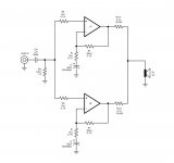
I had another look at the parallel schematic.
I don't think that the two R8 need to be matched, standard 1% should do.
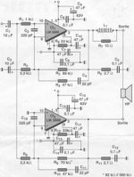
I see they do not show RF attenuation at the inputs.
Add a cap to signal ground from each non-inverting input pin to ground. About 220pF to 1nF would do, the value depending on your speakers' and your ears' bandwidth.
I had another look at the parallel schematic.
I don't think that the two R8 need to be matched, standard 1% should do.
I see they do not show RF attenuation at the inputs.
Add a cap to signal ground from each non-inverting input pin to ground. About 220pF to 1nF would do, the value depending on your speakers' and your ears' bandwidth.
I've wondered about this, too. To get the same voltage drop from the bias current I would also say each +IN should see the same DC impedance like the -IN. I can only speculate that either this wasn't a consideration for the designer or that it was deliberately choosen to cancel (part of) the initial voltage offset with an approbriate current offset?AndrewT said:should Rin be approx half of Rf?
if Rf=20k then Rin =10k.
what do you think?
Gain matching of the parallel halves is as much important as equal dc offset. If gain mismatch produces only, say 200mV output voltage difference with a signal applied we have 1 amp cross current, assuming an unloaded output. With loaded output the parallel halves run at 1 amps current difference.
Close relative matching of the Rf's and Ri's seems to be essential. With 0.1% of 1kohms being 1 ohm, now also the ESR of the Ci parts comes in play...
I would think a procedure like the following might be ok to trim the circuit:
First, try to get a low DC offset for each half and a close match between them, having disconnected the 0R1 output R's and measuring each half indepently. Variation of the 1K0 (Rb) might be the only place to do this (The name Rb, b=bias suggests this), without further parts.
Second, run a broadband signal at full level through the amp (outputs still disconnected) and measure/scope for mimimum AC difference between the outputs. Adjustments could be made by adding trimming Rs (1Meg, 20turn) across the Ri's. If one cannot null the difference at low frequencies, then a capacitance mismatch between the Ci's is obviously the cause. One might circumvent this by using larger values to drop the roll-off way below 1Hz. Then any gain/phase errors will be less severe in their consequences. Also, one might need to add foil bypasses accross the Ci's for matchable gains at higher frequencies.
For the very advisable RF protection, I would suggest a series resistor Rhf in front of Cin together with a capacitor Chf to GND from the junction Rhf to Cs. For a -3dB corner at ~80kHz I would use Rhf=2.2k, Cs=1nF. A small HF ferrite bead directly at the input jack's center pin is also always a good idea, as is capacitive load isolation at the output and the recommend snubbers (like in the datasheet app circuit).
Regards, Klaus
read and implement post30.Scott_drake said:I am having trouble finding 0.1% tolerance resistors, would it be ok to try and match 1% resistors by manually measuring them and finding pairs.
Ah, thanks for that, i have now found a source for .1% resistors, i may still get them as they will be easier to match than 1%. The other option is to get 1% vishale audio grade resistors, which would show greater improvements?
I will also order WIMA caps, any recomendations for other capacitor brands?
I will make the gain around 35, is this enough gain, i am using +&- 36 volt rails.
Is it best to just change Rf when varying the gain of the amp, or should Rin be changed to a higher value as well?
I will also order WIMA caps, any recomendations for other capacitor brands?
I will make the gain around 35, is this enough gain, i am using +&- 36 volt rails.
Is it best to just change Rf when varying the gain of the amp, or should Rin be changed to a higher value as well?
the first paragraph of post30 prompts you to go back and look at the post28 proposal. Did you understand the question?Scott_drake said:I will make the gain around 35, is this enough gain, i am using +&- 36 volt rails.
Is it best to just change Rf when varying the gain of the amp, or should Rin be changed to a higher value as well?
Did you come back for an explanation? Did you bother to read my post?
YES, Rf=Rin. But the parallel version seems to have forgotten that twice the current flows into the chip amp inputs and thus needs a half value Rin to balance out the DC conditions existing on the inverting and non-inverting inputs.
- Status
- This old topic is closed. If you want to reopen this topic, contact a moderator using the "Report Post" button.
- Home
- Amplifiers
- Chip Amps
- Bridged lm3886 suggestions Please