Hi,
a passive volume pot can give very good sound quality.
The selection of the pot and all the surrounding components is a compromise to minimise the deleterious effects of the passive option.
First off you need a lot of information about the source end and what you plan to do with the receive end.
But 50k will not do it.
More like 2k to 10k for a passive pot.
Resistors with 0.1% Tolerance
Not trying to put too fine a point on this minor detail. But, for future reference, it might be worth noting the following.
There's at least one difference between using 0.1%-rated resistors, versus using 1%-rated resistors that have been hand-matched to have resistance values that are within 0.1% of each other:
All of the 0.1%-rated-tolerance resistors that I've seen have a much better Temperature Coefficient than any of the common types of 1%-rated-tolerance resistors.
I don't know if that would be significant, at all, for the application being discussed in this thread. But it could be useful information, for many different applications.
The very-common Xicon 271-series 1% metal film resistors that I often use (1/4W ones are $0.02 each for qty 200, or $0.09 each for qty 10, at mouser.com) have a temperature coefficient spec that's listed as "+/-50 ppm/degC".
But Mouser.com also carries at least two different manufacturers' models/lines of 0.1% resistors:
The IRC RC55-series of 0.1% tolerance resistors have their tempco spec listed as "25 ppm/degC". Mouser stocks about 429 different values of those, which is very nice. Their cost is $0.96 for qty 1 for 10 Ohms to 249K Ohms, or $1.08 for qty 1 for > 249K Ohms. Price break is at qty 50.
The Vishay/Dale PTF-series of 0.1% tolerance resistors are available with three different tempco specs:
"5 ppm/degC", "10ppm/degC", and "15ppm/degC". Unfortunately, Mouser.com only lists a few dozen different available resistance values, for the PTF-series. And they also don't have all tempco (and power rating and voltage rating) options available for every value. Their costs range from $0.81 for qty 1 to $2.40 for qty 1, depending on tempco, value, power rating (1/8W or 1/4W), and max voltage (300v or 500v). Price break is at qty 25.
Note, also, that the Vishay/Dale PTF-series catalog blurbs also say "Very low noise and voltage coefficient. Very good high frequency characteristics." So maybe they're also better than the common 1% resistors in other ways. I don't know. But the datasheets, for all of the different products that they sell, are typically linked directly from each item's listing, on each page of each set of search results, at mouser.com (unlike Digikey.com, where getting the datasheet link requires burrowing down by two pages, for each product), if anyone's interested-enough.
- Tom Gootee
http://www.fullnet.com/~tomg/index.html
Scott_drake said:Ah, thanks for that, i have now found a source for .1% resistors, i may still get them as they will be easier to match than 1%. The other option is to get 1% vishale audio grade resistors, which would show greater improvements?
I will also order WIMA caps, any recomendations for other capacitor brands?
I will make the gain around 35, is this enough gain, i am using +&- 36 volt rails.
Is it best to just change Rf when varying the gain of the amp, or should Rin be changed to a higher value as well?
Not trying to put too fine a point on this minor detail. But, for future reference, it might be worth noting the following.
There's at least one difference between using 0.1%-rated resistors, versus using 1%-rated resistors that have been hand-matched to have resistance values that are within 0.1% of each other:
All of the 0.1%-rated-tolerance resistors that I've seen have a much better Temperature Coefficient than any of the common types of 1%-rated-tolerance resistors.
I don't know if that would be significant, at all, for the application being discussed in this thread. But it could be useful information, for many different applications.
The very-common Xicon 271-series 1% metal film resistors that I often use (1/4W ones are $0.02 each for qty 200, or $0.09 each for qty 10, at mouser.com) have a temperature coefficient spec that's listed as "+/-50 ppm/degC".
But Mouser.com also carries at least two different manufacturers' models/lines of 0.1% resistors:
The IRC RC55-series of 0.1% tolerance resistors have their tempco spec listed as "25 ppm/degC". Mouser stocks about 429 different values of those, which is very nice. Their cost is $0.96 for qty 1 for 10 Ohms to 249K Ohms, or $1.08 for qty 1 for > 249K Ohms. Price break is at qty 50.
The Vishay/Dale PTF-series of 0.1% tolerance resistors are available with three different tempco specs:
"5 ppm/degC", "10ppm/degC", and "15ppm/degC". Unfortunately, Mouser.com only lists a few dozen different available resistance values, for the PTF-series. And they also don't have all tempco (and power rating and voltage rating) options available for every value. Their costs range from $0.81 for qty 1 to $2.40 for qty 1, depending on tempco, value, power rating (1/8W or 1/4W), and max voltage (300v or 500v). Price break is at qty 25.
Note, also, that the Vishay/Dale PTF-series catalog blurbs also say "Very low noise and voltage coefficient. Very good high frequency characteristics." So maybe they're also better than the common 1% resistors in other ways. I don't know. But the datasheets, for all of the different products that they sell, are typically linked directly from each item's listing, on each page of each set of search results, at mouser.com (unlike Digikey.com, where getting the datasheet link requires burrowing down by two pages, for each product), if anyone's interested-enough.
- Tom Gootee
http://www.fullnet.com/~tomg/index.html
Hi Tom,
a very significant difference that you have drawn to our attention.
50ppm over a 50C range amounts to 0.25% variation.
If the hottest to the coolest of the matched pairs is 30C then that reduces the temp induced matching error to just 0.15%.
But I suspect that in our feedback amp that the temp differences between same duty resistors is more likely to be 10C worst case resulting in 0.05% due to temp effects only.
For audio amplifiers, I think 50ppm is good enough if you don't run the resistors hot.
AndrewT said:
But I suspect that in our feedback amp that the temp differences between same duty resistors is more likely to be 10C worst case resulting in 0.05% due to temp effects only.
Everything is moving in the same direction, isn't it ? -- that is -- the R(gain) and R(feedback) are changing by the same percentage.
I just purchase the Xicon's in the 200 pack and match them up-- it only takes a couple of minutes to get a few pairs that are better than 0.1%
Temperature-wise, yes. But as we don't know the exact tempco of the R's they might drift differently or even in opposite directions... one could check that during matching by running enough current through them and see if the matching changes significantly when they get hot. Long term stabilty is also a topic that would favor precisely spec'd mil grade parts. OTOH one would have to make sanity checks how much worst case cross current will flow with the choosen isolation resistors, for paralleled mode. In bridged mode, only offset is an issue whereas slight gain mismatch isn't.jackinnj said:Everything is moving in the same direction, isn't it ? -- that is -- the R(gain) and R(feedback) are changing by the same percentage.
Regards, Klaus
Thank you all for your suggestions, has been very helpful.
Before i go and buy these components, i want your opinion on what to set the gain to. I had originally thought of having it set at 30 ( im using 35 volt rails) .
What would a more suitable or common value be?
Thanks
Before i go and buy these components, i want your opinion on what to set the gain to. I had originally thought of having it set at 30 ( im using 35 volt rails) .
What would a more suitable or common value be?
Thanks
Hi,
a gain of anywhere between 20times (+26db) and 40times (+32db) will work.
To be able to make that decision it is more important to know the range of outputs from your sources after they have passed through your pre-amp. Does it have any gain or is it unity gain?
Your maximum output voltage is near 28Vpk or 20Vac.
A gain of 20Times means that you need ALL your sources to give out more than 1Vac after the pre-amp. If you can't get that high then you need more power amp gain.
Why do you suggest my maximum output voltage is near 28 volts peak, i am running a parrallel configured amp so surely maximum current does not limit this if im running 8ohm speakers?
Why shouldnt it be nearer to 35 volts?
And i also plan on keeping the passive pot as the volume control instead of an active pre. It was said that a 50K pot was too large. I had read that the actual pot i am using was reccomended as a great sounding passive pre.
If someone could please explain this, that would be great.
Thanks
Hi Scott,
the PSU voltage on quiescent load is +-36Vdc.
At full power this will drop by between 1V and 5V depending on the transformer and smoothing etc.
National say that the chipamp drops about 4V through to the load.
If you assume the PSU drops 3V and subtract 4V for the chip drop you end up with near 29Vpk
That is equivalent to 52W into 8r0
I would recommend that 2k to 5k would be best for a passive pre.
This allows a source impedance of upto 200ohms and a Zin at the power amp of as little as 20k to 50k.
Do not use inverting topology with a passive pre. And do ensure you have DC blocking on both the input and the NFB leg.
Hi -
Thanks, could you please tell me what inverting topolgy is, in regards to the passive pot?
I know a higher resistance pot would cause less of a problem to the source signal. But is the promblem to do with the signal impedance seen by the power amp?
The source will see the impedance of the pot in parallel with Rin of the amp. So surely if i keep both impedances as high as possible then it would be ok?
I am obviously wrong so please tell me where i am?
I have attatched some pics to show you the ways i would have configured it, please tell me which one is better?
Attachments
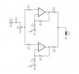
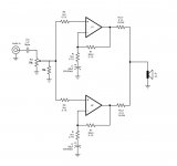
Hi,
both your posts show non-inverting topology.
Both show DC block on the NFB leg.
Both show DC coupling on the input.
The result is that the inputs of both amps see each others impedance and see the pot. The impedance of the pot varies with wiper position.
At the top, maximum volume, the amp input sees the source impedance in series with the DC blocking cap//potvalue//Zin (if fitted).
At the bottom, minimum volume, the amp sees the zero ohms (0r0) // all the others but they are effectively irrelevant.
At very near the middle, about -6db on volume, the amp input sees [potvalue/4]//Zin (if fitted).
The range of resistances seen by the non-inverting input of the amp is from 0r0 to 12k5 (for a 50k pot).
The inverting input sees 20k//1k+series cap.
The unbalanced resistances cause the input offset current to generate an input offset voltage, which also appears at the output as a DC output offset.
As you adjust the volume pot the output offset varies.
The way to cure this is to DC block the input after the pot. The amp then sees Zin//other amp input impedance.
The amp as shown has no RF filter on it's input. That 1k0 is crying out for you to fit a single pole RC filter there on each amp. You can choose anywhere between 220pF and 1.5nF and adjust until you hear the correct amount of treble for your ears and speakers.
Now that you have the filter in place, you will find that it's effect varies as the source impedance (not resistance) increases from zero. At zero volume or maximum volume, the filter is 1k0+C,
at -6db volume the filter is 12k5+1k0 =13k5+C. It has moved down the frequency range by a factor of 13.5 times. This is effectively a variable treble cut filter controlled by the passive pre pot position.
Select a pot <<20% of Zin to ameliorate the variable effect. For Zin~=50k I would try a 2k pot. This presents a maximum source impedance of 500ohms. The RF filter now varies from 1k0 to 1k5 +C. Much better.
Now, can your source drive 2k properly and still produce good quality sound?
Sorry this is so long winded.
It sounds like i might be best to place a buffer between the pot and the amp, then the source will only see the 50k impedance of the pot, and the amp will only see one common low impedance source.
What are some reccomended op-amps or circuits to use for this. Is it a good idea to have some gain in the buffer circuit or just a standard unity gain buffer and leave all the gain to the power amp?
Thanks
Scott
What are some reccomended op-amps or circuits to use for this. Is it a good idea to have some gain in the buffer circuit or just a standard unity gain buffer and leave all the gain to the power amp?
Thanks
Scott
Hi,Scott_drake said:......It sounds like i might be best to place a buffer between the pot and the amp......
not necessarily.
It might be better to use a passive pre-amp.
Just use the lowest pot value that your source can drive well and keep the cables low capacitance and short.
Listening to this low cost set up may convince you not to start experimenting with IC and discrete opamps.
As far as my source driving capabilities, i have a audigy sound card which should be able to drive anything as it can drive headphones. But my main concern is my cd player, i am using the commonly used playstation 1 model spch-1002 with modded output. The outputs come directly from the DAC through 3.3uf wima capacitors so i doubt it will be able to drive very much current at all.
What do you reccomend for lowest impedance for this type of setup, i have no idea of the current capabilities from a DAC. I would like to be able to connect the amp to any source without worrying about what can drive it.
What do you reccomend for lowest impedance for this type of setup, i have no idea of the current capabilities from a DAC. I would like to be able to connect the amp to any source without worrying about what can drive it.
- Status
- This old topic is closed. If you want to reopen this topic, contact a moderator using the "Report Post" button.
- Home
- Amplifiers
- Chip Amps
- Bridged lm3886 suggestions Please