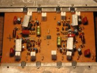
I can't be sure without seeing the schematic, but those diodes may be to help with temperature compensation. They should be mounted on the heatsink if that's the case, but they are shown on the PCB.
You have substituted slower transistors so that will help stability a bit. The design is still fundamentally flawed though.
You have substituted slower transistors so that will help stability a bit. The design is still fundamentally flawed though.
I already tested 2~3 hours long.
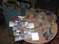
With 3 sets of MOSFETs ( total 12 MOSFETs ).
With 4 SPKs 8ohm 100W series & parallel to get LOAD 8 ohm.
I got headge ( because of Low Frequency )when I tested in my room.
I used equlizer to get more bass.
I think that will be stable if I used good heatsink.
I found that if I used more MOSFETs Heat will reduce.
Now I used very little heatsink.
But I blow air with fan.
That didn't hot in tested condition. ( Only Warm ).
My power supply didn't handle in that condition.
I think AMP can handle MORE POWER.
I think I used more transformer.
Because rail to rail Voltage reduce abt 90 to 73 V.
SPK Out put wave abt +/- 60 V clip deform in supply 73 V condition.
You can see all in my photo.
Attachments
Another alternative of amp with these mosfets : Output power by +/- 40 V - 100 W into 4 Ohms, 200 W in bridge into 8 Ohms. SR 100 V / microsec, 200 V in bridge. SNR over 120 dB. Distortion 1 dB bellow clipping 0.003 %, IMD bellow 0.002 % by this power. Full power up to 300 kHz. Was made several hundred pieces with any problems...
Attachments
Hello Friends,
Thanks For PDF.
Now I will test Subwoofer for that AMP.
http://www.diyaudio.com/forums/showthread.php?s=&threadid=73456&pagenumber=2
Pls, Help me & Advice for my subwoofer which is matched with my AMP.
Thanks For PDF.
Now I will test Subwoofer for that AMP.
http://www.diyaudio.com/forums/showthread.php?s=&threadid=73456&pagenumber=2
Pls, Help me & Advice for my subwoofer which is matched with my AMP.
Hello Friends,
I do new PCB for neat & tidy of my IRF bridge.
I think, My bridge AMP didn't need protection when power On & Off.
Because I didn't hear anything when power On & Off of my bridge AMP.
I think that is because of my IRF AMP design which I got from internet.
Is that true ?
Can u explain why ?
I don't know detail abt my AMP.
Attachments
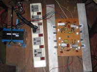
Hello richie00boy,
My schematic is same as old one.
Change in PCB rail line.
Because I faced each other (two amp) in my PCB. U can see in my photo.
So, I changed One circuit.(rotate Transistors,Diodes,Capacitors,Zener,Mosfet to convient with supply rail).
Sorry for my poor english
Difference In power supply.
Now, I used only one Transformer.
Old, Used Two transformers.
Thanks for continue support.
Hello richie00boy,
Is there any other (above 100W AMP) without thermal compensation ?
I don't understand
My AMP is in stable state without thermal compensation, Why?
Now, I already tested my bridge AMP without Fan 3~4hours with two parallel 8 ohm SPKs above 100W output condition.
That amp will blow up after time because it has no thermal compensation.
Is there any other (above 100W AMP) without thermal compensation ?
I don't understand
My AMP is in stable state without thermal compensation, Why?
Now, I already tested my bridge AMP without Fan 3~4hours with two parallel 8 ohm SPKs above 100W output condition.
myanmar said:Hello richie00boy,
Is there any other (above 100W AMP) without thermal compensation ?
Not any good ones.
myanmar said:I don't understand
My AMP is in stable state without thermal compensation, Why?
Now, I already tested my bridge AMP without Fan 3~4hours with two parallel 8 ohm SPKs above 100W output condition.
Then you have been lucky... so far.
hello friends,
Now.
I want to use two rail supply.
that is +/- 80V & +/- 40V use in my that bridge amp.
+/- 80 V supply only for mosfet & +/- 40V supply for the rest.
Can I use two rail supply in my bridge AMP ?
Another one is that can use as Class G ( use relay )?
Pls, Advice & reply.
I want to test that.
What will happen & carful when I test ?
Here is my circuit diagram.
http://www.diyaudio.com/forums/attachment.php?s=&postid=934982&stamp=1149693177
Regards.
Myanmar
One pair of IRF540/9540 can do 100W into 4 ohms as long as the 4 ohms are not too reactive, and the transistors are VERY well cooled. IRFP240/9240 can do the same but with far less restrictions as their case alowes a lot more power dissipation. They are also slightly more linear. An even better combination is IRFP9140 and IRFP240 for reasons i have mentioned about 10 times on this forum.
+-50V rails are the absolute maximum limit for 540/9540. For more than that you need 640/9640, but you will need 2 pairs per amplifier. It would be a better idea to use a slightly higher rail voltage for the driver stage (about 5V higher) to get extra power and reduce heat.
The schematic shows no thermal compensation. Some can be achieved by mounting two of the driver stage transistors on the heatsink. The reason why this amp may not self destruct (but bias will not be thermally stable by any means!) are the source resistors. I know i would never use the amp this way.
ilimzn said:An even better combination is IRFP9140 and IRFP240 for reasons i have mentioned about 10 times on this forum.
I don't think so, it was at least a 100 times...

BTW, what do you think about the combination IRFP9240 to IRFP340 ?
Mike
Thanks for reply & advice.
I want more power.
I want to know is
IRF540 is 100 V in data sheet.
So IRF540&IRF9540 will 200V.
Is that true ?
Can I put +/- 80 V rail for mosfet ?
May that be over current ?
What will be main problem in my circuit ?
Need many MOSFET for parallel ?
( IRF 540 x 2 ) & IRFP240
Which is more power & more stable ?
Because I want to compare for price.
IRFP240 is tribble than IRF540 in my country.
Regards,
Myanmar
IRF540 is 100V so you cannot have more than 100V total across all rails. Think about when one device is only little bit on and the other is fully on.
However, in a bridge amp using 100V devices you can achieve almost 90V swing, which is monster power even into 8 ohms! You would need many parallel devices to cope with this current.
However, in a bridge amp using 100V devices you can achieve almost 90V swing, which is monster power even into 8 ohms! You would need many parallel devices to cope with this current.
- Status
- This old topic is closed. If you want to reopen this topic, contact a moderator using the "Report Post" button.
- Home
- Amplifiers
- Solid State
- Bridge With IRF 540 & IRF 9540