richie00boy said:Any power amp can be bridged provided the power supplies are sharing the same ground.
Also Two Pre-Bridged amps could also be bridged provided the power supplies of that two modules must me seperate and they also feature grounded bridge topology as well
regards to richie00boy,
K a n w a r
I didn't understand my text.jpg ( posted above ).
richie00boy said
Must use 2x impedance for bridge.
If I used a 8ohm 100watts SPK in my bridge ( 4 total MOSFET )
Can SPK handle that bridge power AMP?
Can bridge Power AMP handle that SPK?
If not, Which can be avoid ?
If I parallel two that SPK , how many MOSFET must increase ?
8 or 12 or 16 or 20 or .............
Thanks for reply me.
richie00boy said:But you link the -ve of one amp to the +ve of the other amp to gain a series-connected set of amps?
Certainly yes richie....
myanmar said:I didn't understand my text.jpg ( posted above ).
richie00boy said
Must use 2x impedance for bridge.
If I used a 8ohm 100watts SPK in my bridge ( 4 total MOSFET )
Can SPK handle that bridge power AMP?
Can bridge Power AMP handle that SPK?
If not, Which can be avoid ?
If I parallel two that SPK , how many MOSFET must increase ?
8 or 12 or 16 or 20 or .............
Thanks for reply me.
I didn't understand your jpg either, why you think I can speak German to that level I don't know
")
You seem to be getting a bit confused. A speaker won't care if it gets its power from a bridge or single amp, it's e.g. 100W regardless. Likewise as long as the amp is rated for the load impedance and the speaker can handle the power it's OK.
Please look at my calculations again where I showed you how to work out how many MOSFETs you need. All you need to know is the power of each MOSFET and your desired total power. If you parallel two identical speakers you get half the impedance, i.e. 8 ohms in parallel becomes 4 ohms.
So if your MOSFET is rated at 150W and you derate it to 75% to take account of temperature, this gives you 112.5W RMS to play with. So if you want to achieve a 200W RMS amp you need 2 pairs of MOSFETs, which will leave you with a small safety margin. The maximum realisable would be 225W RMS.
Amp rail voltage can be roughly found by:
Vrail = Vloss + sqrt((2 * Prms) * Z)
where Vloss is typically about 5-10 volts
richie00boy said:But won't the shared ground at the source side upset things especially if an unbalanced input source is used?
Not at all!
Hello Workhorse,
I want to ask about that long time ago.
But my english is very poor.
So, I cannot explain what I want to know.
How many single amp can connect ?
Are there another bridging to get MAX POWER ?
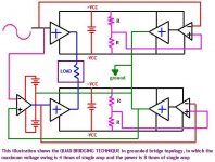
Can I test with 4 power OPAMP ( like TDA 2030 ) in your Quad bridging technique ?
If that's OK, I will test with IRF 540 & 9540.
Must I use 3 separate power supply ?
One is dual supply & the others are single.
Is that true ?
Where can I ground for each OPAMP ?
Can each OPAMP ground to green line ( like in your photo ) ?
Pls, Reply me.
Thanks.
I want to ask about that long time ago.
But my english is very poor.
So, I cannot explain what I want to know.
How many single amp can connect ?
Are there another bridging to get MAX POWER ?
Can I test with 4 power OPAMP ( like TDA 2030 ) in your Quad bridging technique ?
If that's OK, I will test with IRF 540 & 9540.
Must I use 3 separate power supply ?
One is dual supply & the others are single.
Is that true ?
Where can I ground for each OPAMP ?
Can each OPAMP ground to green line ( like in your photo ) ?
Pls, Reply me.
Thanks.
Hello Workhorse,
Can I series with two separate POWER AMP with separate input which is isolated with transformer ?
And then bridge or series with two serried POWER AMP (total 4 power AMP ).
Can I used like that
Start points - & + are join together.
- + - + ----> output 1
+ - + - ----> output 2
OR 4 series POWER AMP.
Pls, explain if u can.
Thanks.
Hi myanmar
Here you have the schematics of one implementation.
In this one, the supply (page-10/10) has a switch (Q510//511//512) who connects the Capacitors (C810 and C812) in parallel or in series depending on the signal amplitude.
In fact you have two power supplies in parallel for low power and in series for high power.
Please note that you could use this in any amplifier topology.
http://www.crownaudio.com/pdf/amps/ma5000vz_schematics.zip
Hello Friends,
Thanks for schematic.zip
I will test my idea later.
My bridge amplifiers are stable now.
tested 3~4 hours
I parallel 2 sets MOSFET ( now total 8 MOSFET ) (two 8 ohm SPk in series).
There is alittle problem
OUTPUT spike when POWER OFF. (heard sound in SPK )
Do I need to increase CAPACITORS ? ( now only 4 X 4700uF ).
ON state OK no problem.
Didn't heard anything.
I think one set of MOSFETs ( 4 mosfet ) can handle at least 100W.
Is that true?
I will try parallel with 3 sets ( total 12 MOSFET ) for 8 ohm load.
For Bridge with +/- 50V supply
My calculation is
Power max for 8 ohm ~ 253Watts.
Power max for 4 ohm ~ 507Watts.
I think 3 set of MOSFETs can handle for 8 ohm load in safe.
If I increase to 6 sets of MOSFETS ( total 24 MOSFETs ) for 4 ohm load ,
Will there be a problem ?
I want to know sure because
I will loose many MOSFETS & SPK if I fail.
Thanks.
Capacitors will do nothing for the pop, that is due to the inherent way the circuit works.
How many MOSFETs you need depends on their power rating and how you derate them, like I keep telling you. Trying to get 100W out of a pair of TO220 MOSFETs is not a good idea IMO. Trying to get 500W out of 3 pairs is guaranteed to blow up at some point, but should be OK for 250W.
How many MOSFETs you need depends on their power rating and how you derate them, like I keep telling you. Trying to get 100W out of a pair of TO220 MOSFETs is not a good idea IMO. Trying to get 500W out of 3 pairs is guaranteed to blow up at some point, but should be OK for 250W.
Hello richie00boy,
I think Slowly power drop will eleminate that pop up when POWER OFF.
So I want to Increase Capacitors.
In our country new or other components are very difficult to find.
But some are very cheaps & very easy to buy ( made in china ).
So, I used that cheap & easy components.
Other circuit design will very hard to find components in our country.
I say again the size of the power supply caps will make no difference. I don't say things for no reason, I have designed and built things for many years now.
I appreciate it might be hard for you to get parts. But you don't need any different parts to make a successful amp, you just need to change the design of the amp because it is flawed.
I appreciate it might be hard for you to get parts. But you don't need any different parts to make a successful amp, you just need to change the design of the amp because it is flawed.
Hello richie00boy,
I forgot to tell you.
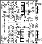
U can see in my photo.
There are two more diode than in earily schematic.
That two diodes are connect with preset above & below.
I don't know why that didn't same PCB & schematic.
I replaced with BC 547 & 557 , BD 139 & 140.
If with that ,
my circuit will stable ?
I forgot to tell you.
U can see in my photo.
There are two more diode than in earily schematic.
That two diodes are connect with preset above & below.
I don't know why that didn't same PCB & schematic.
I replaced with BC 547 & 557 , BD 139 & 140.
If with that ,
my circuit will stable ?
Attachments
- Status
- This old topic is closed. If you want to reopen this topic, contact a moderator using the "Report Post" button.
- Home
- Amplifiers
- Solid State
- Bridge With IRF 540 & IRF 9540