Hi,
I'm not sure what exactly you are asking, but let me give it a try.
1) The relays are actuated in such a way that when changing the volume level, all relays are switched to a "Zero" position to give maximum attenuation.
After 4 msec those relays that should be switched to "One" are told to do so.
As an example: when going from 011111 to 100000, it goes like 011111-000000-100000. You can't hear this 4 msec step in between, but glitches are completely avoided.
2) The output op-amp has a fixed gain when using the Volcb board.
The circuitry before the op-amp is a logarithmic attenuator with steps of resp. 1, 2, 4, 8, 16 and 32 dB, giving a span of 63 dB in 1 dB steps with only 6 relays. This topology needs connections to ground.
The same span of 63 dB to be achieved in a serial way just like an analogue pot, would have needed 64 different resistors plus 63 relays. Not very attractive to my opinion.
hi Hans, thank you for your response.
Understand answer to q1 - all clear on how relays are switched.
And i understand the 2nd answer as well
") What my question really is - since principle of operaiton (output opamp has fixed gain and acts as inverter and VolCB acts as regular attenuator preceding it - as we have seen in many standard designs) - would there be any advantages in using 'original' topology - where attenuator is part of negative feedback. I understand (have done some modelling in spreadsheet) that in that case what one would not have -1dB increment/decrements but IF there is 'quality' benefit to it with standard 1dB attenuator excluding position where gain is infinite (could be done in SW easily) and without adding any other resitors i get following values which may not please some but i think 2dB steps around 0dB gain and then even lower step size (less then 1db) at even lower volumes would be good enough for most of people except those who for some reason need precise 1dB steps of attentuation values.
What my question really is - since principle of operaiton (output opamp has fixed gain and acts as inverter and VolCB acts as regular attenuator preceding it - as we have seen in many standard designs) - would there be any advantages in using 'original' topology - where attenuator is part of negative feedback. I understand (have done some modelling in spreadsheet) that in that case what one would not have -1dB increment/decrements but IF there is 'quality' benefit to it with standard 1dB attenuator excluding position where gain is infinite (could be done in SW easily) and without adding any other resitors i get following values which may not please some but i think 2dB steps around 0dB gain and then even lower step size (less then 1db) at even lower volumes would be good enough for most of people except those who for some reason need precise 1dB steps of attentuation values.What I do NOT know/understand - would original 'topology' provide higher quality / less distortion / better SNR ?
Lastly, i think the only challenge would be how to ensure that middle of the 'attentuator' never gets disconnected but suspect that can be arranged via SW control.
Here is the table i got (using log 1dB relay switched attenuator if connected instead of original pot ):
[special=
(18.3
11.7
7.7
4.7
2.2
0.0
-1.9
-3.6
-5.2
-6.7
-8.1
-9.5
-10.8
-12.1
-13.3
-14.5
-15.7
-16.8
-18.0
-19.1
-20.2
-21.3
-22.4
-23.4
-24.5
-25.6
-26.6
-27.6
-28.7
-29.7
-30.8
-31.8
-32.8
-33.8
-34.8
-35.9
-36.9
-37.9
-38.9
-39.9
-40.9
-41.9
-42.9
-43.9
-45.0
-46.0
-47.0
-48.0
-49.0
-50.0
-51.0
-52.0
-53.0
-54.0
-55.0
-56.0
-57.0
-58.0
-59.0
-60.0
-61.0
-62.0
-63.0
-64.0)
]%[/special]
Hi,hi Hans, thank you for your response.
Understand answer to q1 - all clear on how relays are switched.
And i understand the 2nd answer as well
What I do NOT know/understand - would original 'topology' provide higher quality / less distortion / better SNR ?
Lastly, i think the only challenge would be how to ensure that middle of the 'attentuator' never gets disconnected but suspect that can be arranged via SW control.
Here is the table i got (using log 1dB relay switched attenuator if connected instead of original pot ):
Looking at your table, I'm sure that you haven't used a 2K resistor for R13/R33, for two reasons:
Maximum gain is higher than 6dB and the steps around 0db are very inaccurate.
When needing a higher max gain than 6dB, you should increase R14/R34 instead of decreasing R13/R13, since these resistors are part of the attenuation network.
And no there is no advantage in using the original network.
When using a pot, it is absolutely the best way to implement, but because of the much better properties of precision thin film resistors, distortion goes down, there is no risk of a taper that comes loose and you will have a perfect balance between both channels over the whole range.
And last but not least, you are still using the amp in a virtual ground topology, cancelling the input capacity of the used OPA.
Have a look at the distortion graph I have posted some time ago and compare it to the one in the original article using the pot.
regards,
Hans
Hi,
Looking at your table, I'm sure that you haven't used a 2K resistor for R13/R33, for two reasons:
Maximum gain is higher than 6dB and the steps around 0db are very inaccurate.
When needing a higher max gain than 6dB, you should increase R14/R34 instead of decreasing R13/R13, since these resistors are part of the attenuation network.
And no there is no advantage in using the original network.
When using a pot, it is absolutely the best way to implement, but because of the much better properties of precision thin film resistors, distortion goes down, there is no risk of a taper that comes loose and you will have a perfect balance between both channels over the whole range.
And last but not least, you are still using the amp in a virtual ground topology, cancelling the input capacity of the used OPA.
Have a look at the distortion graph I have posted some time ago and compare it to the one in the original article using the pot.
regards,
Hans
Tx Hans - all clear.
I did not use original schematic ... all i did was reverse re-engineer what would be ratio of 2 sides of attentuator for 0,1,2,3 etc dB attenuation and then built a table assuming attenuator is logarithmic and yes that is why 1st element i dropped (infinity dB gain) but the rest are i am pretty sure correct - can share spreadsheet if you wish.
... anhyhow, what you are confirming - whether it is in feedback loop or it is acting as attenuator between signal and (virtual) ground - performance is expected to be the same. That's ALL i wanted to know
)Thank you for sharing your knowledge with us !!!
I've got both versions of this preamp, and my preliminary distortion measurements show a small advantage of the pot version.
I made the measurements using a very clean 1kHz generator, a Hall topology notch filter followed by a 60dB low-noise amplifier. The signals were acquired by a MOTU Audio Express sound interface that I modified for lower distortion.
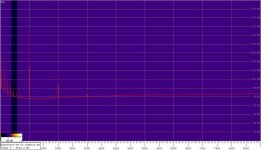
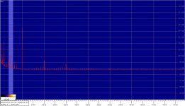
I'm enclosing the spectra obtained at an input level of +11dBu, preamp gain of 0dB, acquisition 24/48, FFT length of 524288 points, 32 averages per Welch.
The first spectrum is for the pot version; the 3rd harmonic is 20dB lower than the second one, and the THD for the two harmonics is -126.8dB.
The second spectrum is for the ladder attenuator; while the 2nd harmonic is the same as before, the 3rd one is 10dB stronger than before, but the THD is practically the same (-126.7dB) due to the quadratic summation of the two harmonics' levels.
Note that the notch filter attenuation of the respective harmonics has been accounted for in the THD calculations.
Regards,
Braca
P.S. Apologies for the bad background colour choice in the first attachment.
I made the measurements using a very clean 1kHz generator, a Hall topology notch filter followed by a 60dB low-noise amplifier. The signals were acquired by a MOTU Audio Express sound interface that I modified for lower distortion.
I'm enclosing the spectra obtained at an input level of +11dBu, preamp gain of 0dB, acquisition 24/48, FFT length of 524288 points, 32 averages per Welch.
The first spectrum is for the pot version; the 3rd harmonic is 20dB lower than the second one, and the THD for the two harmonics is -126.8dB.
The second spectrum is for the ladder attenuator; while the 2nd harmonic is the same as before, the 3rd one is 10dB stronger than before, but the THD is practically the same (-126.7dB) due to the quadratic summation of the two harmonics' levels.
Note that the notch filter attenuation of the respective harmonics has been accounted for in the THD calculations.
Regards,
Braca
P.S. Apologies for the bad background colour choice in the first attachment.
Attachments
I've got both versions of this preamp, and my preliminary distortion measurements show a small advantage of the pot version.
I made the measurements using a very clean 1kHz generator, a Hall topology notch filter followed by a 60dB low-noise amplifier. The signals were acquired by a MOTU Audio Express sound interface that I modified for lower distortion.
I'm enclosing the spectra obtained at an input level of +11dBu, preamp gain of 0dB, acquisition 24/48, FFT length of 524288 points, 32 averages per Welch.
The first spectrum is for the pot version; the 3rd harmonic is 20dB lower than the second one, and the THD for the two harmonics is -126.8dB.
The second spectrum is for the ladder attenuator; while the 2nd harmonic is the same as before, the 3rd one is 10dB stronger than before, but the THD is practically the same (-126.7dB) due to the quadratic summation of the two harmonics' levels.
Note that the notch filter attenuation of the respective harmonics has been accounted for in the THD calculations.
Regards,
Braca
P.S. Apologies for the bad background colour choice in the first attachment.
hi Braca, tx for sharing. I have no clue if anyone could hear a difference but i did see while ago articles claiming that one of the aspects to sound quality is absence/presence of odd harmonics ... and funniest part was that it was not the absolute amount (% or dB) but relative to even harmonics ... so e.g. 0.01% of 3rd or 5th harmonic distortion was very much heard when even order harmonic distortion was 0.01% as well but lot less so when even order distortion was much higher (e.g. 0.1% in this example).
Either way - do you have an opinion on why it measured worse with ladder attenuator? My primitive semi-educated feeling is that if op-amp was ideal and there was some distortion due to the ladder (or pot) ... then in case of attenuator before opamp - if anything get's distorted prior - thats what you get at the output, but in case of pot ('distorting element') being part of feedback loop - result might be better ?
I could be very wrong.... but just really curious !
output opamp has fixed gain and acts as inverter and VolCB acts as regular attenuator preceding it - as we have seen in many standard designs) - would there be any advantages in using 'original' topology - where attenuator is part of negative feedback.
[/SPECIAL]
I thought the VolCB replaced the pot in the feedback circuit. Is this not correct?
Nope.I thought the VolCB replaced the pot in the feedback circuit. Is this not correct?
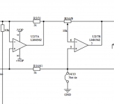
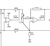
here is VolICB Schematic
http://www.diyaudio.com/forums/attachments/group-buys/546056d1461848577-maya-r2r-advanced-volume-controller-relay-board-jpg
and here is original Bruno's schematic followed by Hans/VolCB (resistor numbers reflect those in Hans' schematic)
Sorry for ugly drawings but hope it's clear.
Attachments
hi Braca, tx for sharing. I have no clue if anyone could hear a difference but i did see while ago articles claiming that one of the aspects to sound quality is absence/presence of odd harmonics ... and funniest part was that it was not the absolute amount (% or dB) but relative to even harmonics ... so e.g. 0.01% of 3rd or 5th harmonic distortion was very much heard when even order harmonic distortion was 0.01% as well but lot less so when even order distortion was much higher (e.g. 0.1% in this example).
Either way - do you have an opinion on why it measured worse with ladder attenuator? My primitive semi-educated feeling is that if op-amp was ideal and there was some distortion due to the ladder (or pot) ... then in case of attenuator before opamp - if anything get's distorted prior - thats what you get at the output, but in case of pot ('distorting element') being part of feedback loop - result might be better ?
I could be very wrong.... but just really curious !
I'm still wondering about this result myself. Actually, I expected more distortion from the pot version of my two preamps because this one has also a 1K resistor in series with the pot for preventing possible loudspeaker failure, which is known for the potential to generate distortion.
In any case, the distortion level is so low that it would hardly matter when listening to the music.
Regards,
Braca
With all respect for the time you have taken for your measurements, I have a few remarks:I've got both versions of this preamp, and my preliminary distortion measurements show a small advantage of the pot version.
I made the measurements using a very clean 1kHz generator, a Hall topology notch filter followed by a 60dB low-noise amplifier. The signals were acquired by a MOTU Audio Express sound interface that I modified for lower distortion.
I'm enclosing the spectra obtained at an input level of +11dBu, preamp gain of 0dB, acquisition 24/48, FFT length of 524288 points, 32 averages per Welch.
The first spectrum is for the pot version; the 3rd harmonic is 20dB lower than the second one, and the THD for the two harmonics is -126.8dB.
The second spectrum is for the ladder attenuator; while the 2nd harmonic is the same as before, the 3rd one is 10dB stronger than before, but the THD is practically the same (-126.7dB) due to the quadratic summation of the two harmonics' levels.
Note that the notch filter attenuation of the respective harmonics has been accounted for in the THD calculations.
Regards,
Braca
P.S. Apologies for the bad background colour choice in the first attachment.
In case of 0dB gain, the VolCB has only 6 relais in series with the gain resistors R13 / R14.
When this set-up would show more 3rd H distortion, it can only be that the relais are causing this since nothing else is in the chain, a bit unlikely to my feeling.
But on the other hand, did you use the same BPBP for both recordings, where only the pot was replaced for the VolCB ?
If not, every single component is different, which makes it hard if not impossible to compare pot/VolCB distortion from one topology to the other.
Measured THD with -126 dB or 0,00005%, is fantastic and even slightly better as expected with the 0,00004% THD according to TI spec's at +/-12 V supply and 11 dBU input for one single LM4562.
For 3 op-amps in series as in the BPBP, this then would mathematically result in 0,00007% THD.
Hans
Nope.
here is VolICB Schematic
http://www.diyaudio.com/forums/attachments/group-buys/546056d1461848577-maya-r2r-advanced-volume-controller-relay-board-jpg
and here is original Bruno's schematic followed by Hans/VolCB (resistor numbers reflect those in Hans' schematic)
Sorry for ugly drawings but hope it's clear.
Thanks hanswolek for clearing this up. It was not apparent to me in Han's schematic.
With all respect for the time you have taken for your measurements, I have a few remarks:
In case of 0dB gain, the VolCB has only 6 relais in series with the gain resistors R13 / R14.
When this set-up would show more 3rd H distortion, it can only be that the relais are causing this since nothing else is in the chain, a bit unlikely to my feeling.
But on the other hand, did you use the same BPBP for both recordings, where only the pot was replaced for the VolCB ?
If not, every single component is different, which makes it hard if not impossible to compare pot/VolCB distortion from one topology to the other.
Measured THD with -126 dB or 0,00005%, is fantastic and even slightly better as expected with the 0,00004% THD according to TI spec's at +/-12 V supply and 11 dBU input for one single LM4562.
For 3 op-amps in series as in the BPBP, this then would mathematically result in 0,00007% THD.
Hans
Hans,
ZERO issues from my side. OBVIOUSLY based on your measrumenets as well as Bruno's originally - attenuator approach obviously works FANTASTICLY well !!!
i was just curious if slightly different (and uglier of course) design should be positioned to work any better ... if not ... all good
Your comments are appreciated.With all respect for the time you have taken for your measurements, I have a few remarks:
In case of 0dB gain, the VolCB has only 6 relais in series with the gain resistors R13 / R14.
When this set-up would show more 3rd H distortion, it can only be that the relais are causing this since nothing else is in the chain, a bit unlikely to my feeling.
But on the other hand, did you use the same BPBP for both recordings, where only the pot was replaced for the VolCB ?
If not, every single component is different, which makes it hard if not impossible to compare pot/VolCB distortion from one topology to the other.
Measured THD with -126 dB or 0,00005%, is fantastic and even slightly better as expected with the 0,00004% THD according to TI spec's at +/-12 V supply and 11 dBU input for one single LM4562.
For 3 op-amps in series as in the BPBP, this then would mathematically result in 0,00007% THD.
Hans
The two preamps are not identical - the PCB's are, and the active and passive components come from the same respective orders, but this is where it ends.
The pot version has a headphone amplifier in the same casing, which is permanently connected to the BPBP output.
The other preamp shares the casing with the attenuator, whose digital signals may be a factor in the increased 3rd harmonic - the spikes above the noise floor originate probably from it.
In order to get an idea of the accuracy of my THD measurement I made another one at +4dBu, and then extrapolated the results to +18dBu, where Bruno measured a THD of -120dB at the same gain. My extrapolated result was -117dB, which I think is not bad for a DIY measurement chain.
Regards,
Braca
I've still not finished building mine because I keep wanting to get everything right first time, case design etc... So, I'm forgetting that for now and just going to get something running.
My question is, could someone quickly run over the double pot idea for setting the range of the main volume pot?
From memory, it simply involved a second pot in parallel, one that would be for adjustment only. If that's correct, would it also be 10k or a different value?
My question is, could someone quickly run over the double pot idea for setting the range of the main volume pot?
From memory, it simply involved a second pot in parallel, one that would be for adjustment only. If that's correct, would it also be 10k or a different value?
To be able to set the limits/range of the volume control but without using fixed resistors.
I'm sure someone said, on one of these threads, that a second pot can be used in parallel and it wouldn't effect linearity like fixed resistors would.
The aim though, in not using fixed resistors around the pot, would be to allow tweaking of the volume range as I get used to it.
I'm sure someone said, on one of these threads, that a second pot can be used in parallel and it wouldn't effect linearity like fixed resistors would.
The aim though, in not using fixed resistors around the pot, would be to allow tweaking of the volume range as I get used to it.
Last edited:
See posting #418.
It concerned placing a second pot in series, not parallel, to a volume pot to adjust max vol setting.
Hans
Oh.... series.
Thanks for that memory refresh Hans, I knew I'd asked it before but couldn't find the posts, in what context I'd asked.. Now found, with your replies.
Last edited:
- Home
- Source & Line
- Analog Line Level
- BPPBP - Bruno Putzey's Purist Balanced Preamp (well a balanced volume control really)