Interestingly, it looks as through Jeff Rowland are using the CS3310 (a low voltage version of the TI PGA23xx +-15V active volume control/buffer) as the main gain element. Further, they are using it in 'balanced' mode just as I did in my 'Symphony' preamp I designed in 2010 - details on my website.
There is some tech info here:
Jeff Rowland :: Digital Volume Control: DACs versus the Crystal Semiconductor CS3310
Jan
Very tech info. An ad blurb defending the use of a bad sounding cheap-skate solution that even 22 years ago was a pathetic excuse for a volume control. Complete with cheap opamps too.
It was probably meant to badmouth ML who were using dac chips as volume controls at the time.
Thank you for this. Probably the most useful comment from this entire thread as far as i am concerned.
(pssst.. what is a "DCB1" ? )
If you try to Google it , something like this shows up (and a lot more):(pssst.. what is a "DCB1" ? )
Salas hotrodded blue DCB1 build
Very tech info. An ad blurb defending the use of a bad sounding cheap-skate solution that even 22 years ago was a pathetic excuse for a volume control. Complete with cheap opamps too.
It was probably meant to badmouth ML who were using dac chips as volume controls at the time.
Wow. Thanks for the insight!
Jan
Interestingly, it looks as through Jeff Rowland are using the CS3310 (a low voltage version of the TI PGA23xx +-15V active volume control/buffer) as the main gain element. Further, they are using it in 'balanced' mode just as I did in my 'Symphony' preamp I designed in 2010 - details on my website.
I used its cousin, the CS3318 which is an 8-channel version, with +/- 9V supply, in several designs. Also in a 6-channel active xover. It is a very clean sounding unit, pretty transparent. A lot of thinking went into it.
Are you still using it?
Jan
I bought and installed the quite expensive Putzeys' regulators.What regulators did you use for the G Word?
I am not sure they were worth the money. But I cannot assess that until after I change the transformer.
And I had to alter them to increase the cooling and allow them to operate at a lower temperature.
Part of that high temperature is because he used regulated power to supply the relays. And he used 12V relays without current saving when almost 30Vdc was available at the power input. Three 24V relays with current saving would take ~10mA, whereas three 12V relays without current saving take ~35mA and all of that from the regulators.
Last edited:
I didn't follow this thread for quite some time, but I can see that there is still a lot of confusion around pots.
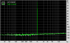
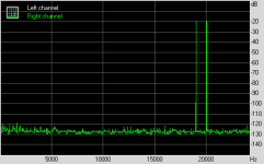
Without going into any detail or commenting on different topologies, I have included THD and IMD images below, showing the immaculate performance of the "Hans" volume control board.
Hans
Without going into any detail or commenting on different topologies, I have included THD and IMD images below, showing the immaculate performance of the "Hans" volume control board.
Hans
Attachments
The second pot (identical to the vol pot) serves the purpose of preventing too much gain, has to be set once and never be touched again.Hi Hans,
If one choose to add 2nd pot as a variable resistor Z, how such a composite should be wired and whether both pots should be on the same axis in order to have the same rotational angle/value...like in sch below?
This means that the axes are not coupled.
Put your volume pot in the max position and then turn the second to a position where you have something like +6dB or whatever you need as maximum gain.
That's it and all the goodies of the BPBP will stay intact.
Hans
")
I have a basic question:
What AC voltage are people feeding their boards/rectifiers? Is there an optimal DC voltage for the Hypex regs in the 15V-40V spec?
I am getting my transformer from scrap sources - basically linear wallwarts or scavenged from other bits and pieces.
I have a transformer from a 15 DC power supply but which reads 15V AC internally? It is old so may be expecting higher mains voltage in the UK. My mains measures ~235V . Appears to be dead at the DC level, suspect the rectifier is gone.
I have a wallwart that outputs 18V AC ~500mA. I have a linear 30V DC PSU ..
Which, if any might be suitable (using their internal transformers)? What minimum current draw do I need ?
The maximum current draw from the PSU measured in my two preamps is 90mA in the positive rail (Input #2 selected), and 70mA in the negative one.
Given that the HxR have a max. output voltage of 12.5V and need a 3V dropout voltage for good operation, the rectifier/filter should provide a bit more than 15.5V, but not much more for the regulators are located close to the electrolytics caps on the PCB, and the reg dissipation should thus be kept at a minimum.
Hope this helps.
Regards,
Braca
Maplins do a 12-0-12 250mA for about £6. I get 13.7v out on my slightly high 242V mains.
12V 250mA Miniature Transformer | maplin
12V 250mA Miniature Transformer | maplin
Hmm... It looks like I'm confused about how to work out what AC I need for the rectification circuit/capacitors on the BPPBP board. Is the old 1.414 ratio for AC Vpeak and not Vrms?
Simon, is that 13.7v transformer output going to give you what the Hypex appear to need, 15.5V DC?
A quick check with my MM gives me 247V mains. Quite high I guess. I shall have to actually measure what I already have.
Simon, is that 13.7v transformer output going to give you what the Hypex appear to need, 15.5V DC?
A quick check with my MM gives me 247V mains. Quite high I guess. I shall have to actually measure what I already have.
The second pot (identical to the vol pot) serves the purpose of preventing too much gain, has to be set once and never be touched again.
This means that the axes are not coupled.
Put your volume pot in the max position and then turn the second to a position where you have something like +6dB or whatever you need as maximum gain.
That's it and all the goodies of the BPBP will stay intact.
Hans
Hans, if it was properly explained earlier and i failed to understand it - sorry about the question - pls point me in the right direction. It is about original/core design not 2 pots in series:
What I did not understand is the need to connect resistors in the attenuator the the ground line. My intuition tells me that if that did NOT exist, there is risk if one of the relays is too slow that volume jumps to infinity etc ... though it could be solved in SW ... BUT what i do not understand electrically - i think some current would need to go to ground line and then what is the math behind it ?
My 'gut' (no brains) thinks that voltage at 'viper' coming into opamp is always (in theory) zero ... does it mean current to 'ground' will also be 0 ?
Sorry for dumb question ...
Hi,Hans, if it was properly explained earlier and i failed to understand it - sorry about the question - pls point me in the right direction. It is about original/core design not 2 pots in series:
What I did not understand is the need to connect resistors in the attenuator the the ground line. My intuition tells me that if that did NOT exist, there is risk if one of the relays is too slow that volume jumps to infinity etc ... though it could be solved in SW ... BUT what i do not understand electrically - i think some current would need to go to ground line and then what is the math behind it ?
My 'gut' (no brains) thinks that voltage at 'viper' coming into opamp is always (in theory) zero ... does it mean current to 'ground' will also be 0 ?
Sorry for dumb question ...
I'm not sure what exactly you are asking, but let me give it a try.
1) The relays are actuated in such a way that when changing the volume level, all relays are switched to a "Zero" position to give maximum attenuation.
After 4 msec those relays that should be switched to "One" are told to do so.
As an example: when going from 011111 to 100000, it goes like 011111-000000-100000. You can't hear this 4 msec step in between, but glitches are completely avoided.
2) The output op-amp has a fixed gain when using the Volcb board.
The circuitry before the op-amp is a logarithmic attenuator with steps of resp. 1, 2, 4, 8, 16 and 32 dB, giving a span of 63 dB in 1 dB steps with only 6 relays. This topology needs connections to ground.
The same span of 63 dB to be achieved in a serial way just like an analogue pot, would have needed 64 different resistors plus 63 relays. Not very attractive to my opinion.
- Home
- Source & Line
- Analog Line Level
- BPPBP - Bruno Putzey's Purist Balanced Preamp (well a balanced volume control really)