Hey guys,
I bought the boyuu a9 three years ago. I struggled alot, because I hadn't any clue how the amplifier works.
Now I wouldn't say, that I know anything more than before. When I turned the amplifier on a humming sound gets louder. When I use the pontiometer to control the volume I can control the volume of the humming noise. The humming comes without any source. When I try to play some music, the music sounds really bad when I raise the volume. The Lepai LP-2020A+ sounds way better. I try to use the boyuu a9 with my Heco Celan 300 on 4 Ohm.
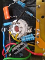
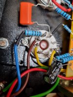
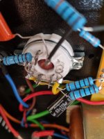
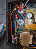
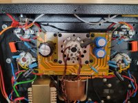
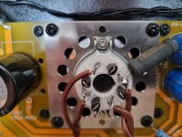
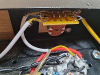
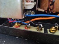
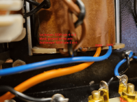
I think there many failure in my cable management. Would you guys do me a favour and give me some hints? The yellow wire from 7 and 2, which is connected to the other tube; is it important that the yellow wire from 2 goes to 2, or doesn't matter?
Also my on/off switch isn't working. Both states are "on". When I check with my multimeter I got continuity on both positions.
Best regards! And I'm, sorry for my crappy english.
René
I bought the boyuu a9 three years ago. I struggled alot, because I hadn't any clue how the amplifier works.
Now I wouldn't say, that I know anything more than before.
When I turned the amplifier on a humming sound gets louder. When I use the pontiometer to control the volume I can control the volume of the humming noise. The humming comes without any source. When I try to play some music, the music sounds really bad when I raise the volume. The Lepai LP-2020A+ sounds way better. I try to use the boyuu a9 with my Heco Celan 300 on 4 Ohm.I think there many failure in my cable management. Would you guys do me a favour and give me some hints? The yellow wire from 7 and 2, which is connected to the other tube; is it important that the yellow wire from 2 goes to 2, or doesn't matter?
Also my on/off switch isn't working. Both states are "on". When I check with my multimeter I got continuity on both positions.
Best regards! And I'm, sorry for my crappy english.
René
Attachments
-
 20220205_133310.jpg363.8 KB · Views: 158
 -
 20220205_133315.jpg396.5 KB · Views: 145
 -
 20220205_133323.jpg330.3 KB · Views: 177
 -
 20220205_133331.jpg398.6 KB · Views: 152
 -
 20220205_133335.jpg487.8 KB · Views: 162
 -
 20220205_133340.jpg435.9 KB · Views: 151
 -
 20220205_133347.jpg335.2 KB · Views: 142
 -
 20220205_133359.jpg323.1 KB · Views: 141
 -
 20220205_133407.jpg547.8 KB · Views: 140
 -
 20220205_133417.jpg375.3 KB · Views: 131
 -
 20220205_133427.jpg401.3 KB · Views: 137
 -
 20220205_133435.jpg329.8 KB · Views: 140
 -
 20220205_133437.jpg324.2 KB · Views: 126
 -
 20220205_133443.jpg345.7 KB · Views: 117
 -
 20220205_133448.jpg508.3 KB · Views: 127
 -
 20220205_133453.jpg331.2 KB · Views: 124
 -
 20220205_133458.jpg277.2 KB · Views: 129
 -
 20220205_133503.jpg358.3 KB · Views: 118
 -
 20220205_133508.jpg373 KB · Views: 118
 -
 20220205_133531.jpg381 KB · Views: 147
Are the two 6.3 V windings earthed? They should be, and if missing could well be causing hum.
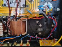
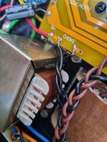
If I follow the filament wiring for the EL34's I don't see any connection to earth. Do the windings for 6.3 V perhaps have centre-taps that are earthed? But I don't see wires for that coming out of the power transformer.
If I follow the filament wiring for the EL34's I don't see any connection to earth. Do the windings for 6.3 V perhaps have centre-taps that are earthed? But I don't see wires for that coming out of the power transformer.
If there is no center tap on the 6.3V winding(s) that you can connect to ground, then . . .
Do not ground one end of the 6.3 winding, instead connect two 100 Ohm resistors, each resistor to different ends of the 6.3V, and then connect the other ends of the 100 Ohm resistors to ground (that forms a virtual center tap to ground).
Then make sure that the B+ secondary center tap connects directly to the minus (-) end of the first filter cap.
Do not connect the center tap directly to the amplifier central ground point, instead, connect the minus (-) end of the first filter cap, and from there, use a separate wire to connect to the minus (-) end of the second filter cap; then a third wire from the second cap minus (-) to the amplifier central ground point.
PCBs make it harder to modify an improperly constructed amplifier to correct ground loops that cause hum.
The RCA input jacks also have to be done properly, that is another post (later if you need info on that)
My worst vacuum tube amplifier has 500uV hum (it has a no-no . . . a magnetic steel chassis), all the other amplifiers I designed and built have less than 100uV hum. I learned so many tricks along the way, to get the hum that low.
Good morning everbody,
thanks for your quick responses and the deatailed answers.
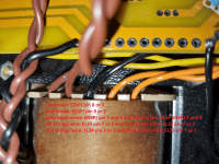
Do you mean all of them? So the both orange wires (6.3V/AC 4A, EL34) and both black wires (6.3V/AC 2A 6N2J)? Should I connect them to the groundboard of the pcb or do you mean the real earth of the socket, which is, in my case the green wire? Thank you for your upcoming answer.
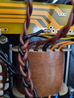
#Edit.## now i googled a little bit. The center tap could be a wire. But I think as 6A3sUMMER mentioned, I haven't got a center tap on the main transformer. You can see all of my wires in the both pictures.
@6A3sUMMER before I raise the iron I'd rather ask before. Do I understood everything right? So after the 100 Ohm resistor, I connect either pin 2 or 7 and the ground of the pcb and also the other EL34? Should I do the same with the other 6.3V (black wires | 2A) for the 6N2J?

I absolutly don't get the second part. Because I don't know which one of the wires and caps are the right.
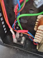
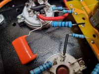
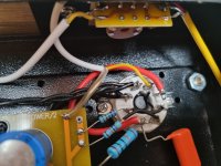
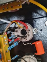
The brown thick wire of of the transformator is the secondary center tap, or? The first filter cap it the black one which is directly connected to the socket? And the second filter cap the blue ones on the pcb? Or is it the second black cap to the left?
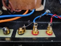
@PrebenK can you make some marks on the bad solders, I doesn't know which one is bad. Two or three are enought, than I can check for more!
As I said before, thank you so much guys!
thanks for your quick responses and the deatailed answers.
two 6.3 V windings earthed?
Do you mean all of them? So the both orange wires (6.3V/AC 4A, EL34) and both black wires (6.3V/AC 2A 6N2J)? Should I connect them to the groundboard of the pcb or do you mean the real earth of the socket, which is, in my case the green wire? Thank you for your upcoming answer.
#Edit.## now i googled a little bit. The center tap could be a wire. But I think as 6A3sUMMER mentioned, I haven't got a center tap on the main transformer. You can see all of my wires in the both pictures.
@6A3sUMMER before I raise the iron I'd rather ask before. Do I understood everything right? So after the 100 Ohm resistor, I connect either pin 2 or 7 and the ground of the pcb and also the other EL34? Should I do the same with the other 6.3V (black wires | 2A) for the 6N2J?
I absolutly don't get the second part. Because I don't know which one of the wires and caps are the right.
The brown thick wire of of the transformator is the secondary center tap, or? The first filter cap it the black one which is directly connected to the socket? And the second filter cap the blue ones on the pcb? Or is it the second black cap to the left?
@PrebenK can you make some marks on the bad solders, I doesn't know which one is bad. Two or three are enought, than I can check for more!
As I said before, thank you so much guys!
Attachments
Yes, both have to be earthed/grounded in one way or another.
I don't want to belittle the proposal/advise 6A3sUMMER gave in any way (creating a virtual ground with two resistors per 6.3 V winding; your drawing of it is wrong b.t.w.) but in my experience this is not necessary in most cases when dealing with a two stage amplifier like yours. You could first try the simple way (only two wires have to be added, one per 6.3 V winding). If that doesn't work, you could always try the virtual ground.
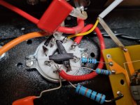
For the supply of the EL34's the simple way would be to solder a wire between ground and one of the two pins on the socket where an orange wire 'meets' a yellow wire (it doesn't matter which of the two pins you choose).
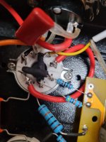
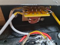
Than do the same for the other winding. So solder a wire between ground and one of the two pins where a black wire coming from the power transformer 'meets' a black wire going to the other tube socket (it again doesn't matter which of the two pins you choose).
I don't want to belittle the proposal/advise 6A3sUMMER gave in any way (creating a virtual ground with two resistors per 6.3 V winding; your drawing of it is wrong b.t.w.) but in my experience this is not necessary in most cases when dealing with a two stage amplifier like yours. You could first try the simple way (only two wires have to be added, one per 6.3 V winding). If that doesn't work, you could always try the virtual ground.
For the supply of the EL34's the simple way would be to solder a wire between ground and one of the two pins on the socket where an orange wire 'meets' a yellow wire (it doesn't matter which of the two pins you choose).
Than do the same for the other winding. So solder a wire between ground and one of the two pins where a black wire coming from the power transformer 'meets' a black wire going to the other tube socket (it again doesn't matter which of the two pins you choose).
Last edited:
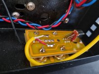
Hey PFL200, I added two small wires from the pcb ground to the pins. My earth isn't connected to the pcb ground, is that correct? I have seen some pictures where people connected the earth with the pcb. Mine is connected through a bolt with the housing. Best regards.
b.t.w. this is the language I understand.
"[...] two pins on the socket where an orange wire 'meets' a yellow wire (it doesn't matter which of the two pins you choose)."
b.t.w. this is the language I understand.
"[...] two pins on the socket where an orange wire 'meets' a yellow wire (it doesn't matter which of the two pins you choose)."
Later on I connect the earth to the pcb ground. Some guys do it, some guys leave it like that. My screw isn't connected to the earth, just the case.
Your solutions worked really fine for me, when I play nothing still a little bit of a humming noise, but I think this is normal, or?
Speaker now much louder, more clear and more bass. Thank you so much.
I'm still open for advices.
#Edit.##, I'm still impressed. Two little wires, the volume increased huge! I never owned a tube amp, the tubes are now getting warmer then before. Its okay when they get hot, or? Later on I can measure the temperature.
Your solutions worked really fine for me, when I play nothing still a little bit of a humming noise, but I think this is normal, or?
Speaker now much louder, more clear and more bass.
Thank you so much.I'm still open for advices.
#Edit.##, I'm still impressed. Two little wires, the volume increased huge! I never owned a tube amp, the tubes are now getting warmer then before. Its okay when they get hot, or? Later on I can measure the temperature.
I assume the case is made of metal. If so: Is the case connected to earth (coming from the three prong mains connector)? If yes, does the screw/bolt make a connection between the case and PCB ground?
Is the source you are using unearthed (meaning: does it have a mains plug with only two leads, so without an earth connection, like for instance CD-players have)?
Is the source you are using unearthed (meaning: does it have a mains plug with only two leads, so without an earth connection, like for instance CD-players have)?
1. The idea of connecting a center tap, or 2-resistor virtual center tap to ground . . . is so that the two filament ends will be 3.15V above ground; instead of one filament end at 6.3V above ground, and the other filament end 0V above ground.
2. An input tube that has an un-bypassed cathode can inject power mains frequency from the filament, and if there is higher frequency noise on the filament winding, will very easily inject that noise into the cathode.
An example would be the noise from a B+ winding on the same transformer, that has a capacitor input filter for the B+ circuit.
3. For an SRPP, or other similar floating cathode on the top tube, any filament power main frequency, and any noise on the filament winding will be injected into the top cathode of the SRPP.
So, use the center tap, or the virtual center tap, and instead of connecting it to ground, connect a two resistor resistive divider from B+ to ground. Connect the junction of the resistive divider to the center tap or virtual center tap.
Then connect a bypass cap from there to ground.
The correct DC voltage is found by the two cathode voltages of the SRPP, and the filament to cathode voltage ratings (+ and -), and also how far the top cathode will swing at maximum signal.
There are examples of good voltage selections versus those parameters.
Also, a concertina phase splitter has the same problem, the filament can inject power frequency and noise into the cathode.
The same technique of raised DC voltage, with bypass capacitor to ground, can fix that problem.
Use the technique in number 3. above.
I had an amplifier that really suffered from this problem, it needed the elevated filament mod with resistors and bypass capacitor.
Over the years, I have seen Boyuu original or modified schematics that had un-bypassed cathode parallel input triode(s), and SRPP input stages.
Those can have hum and noise injected into the cathodes.
Some tubes are better than others at rejecting that hum and noise, but the SRPPS should have elevated filaments with bypass caps from the elevated DC to ground.
Just my opinions.
Last edited:
Hey guys,
now I tried a few things.
After the ALPS 27 arrives I try the idea of 6A3sUMMER.
Right now I'm a little bit dissapointed with the amplifier. Maybe I'm not the guy for tube amplifiers. I use Heco Celan 300 with the Boyuu. In my humble opinion the kickbass is missing. In general I notice a lack of bass. When I hear a acustic guitar, It sounds really great. Still I'm the guy hearing Eminem/50-Cent etc.
@PFL200 I tried to connect the earth to the main ground board. After that I got humming noise on the cinch channel. When I raised the volume, the humming raised also.
So right now:
If yes, does the screw/bolt make a connection between the case and PCB ground?
No, because of the problem of humming.
Is the source you are using unearthed (meaning: does it have a mains plug with only two leads, so without an earth connection, like for instance CD-players have)?
I'm using my computer as input. 3,5mm jack plug.
Best regards and feel free about more information.
#.Edit##
Is it possible that the amplifier sounds better when the socket earth is connected to the ground board? I think there was more bass.
Last edited:
- Home
- Amplifiers
- Tubes / Valves
- Boyuu EL34 A9 Tube Amp