you will find divider calculators on the internet, it's simple to use, you just need to know your input voltage and what you want output, example:You found changing cap 102 and 202 gave you improvements?
Can you further explain the voltage divider calculator. I don't get it.
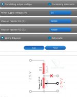
input voltage 2v =
0.750v output voltage
resistance 1 (signal) -10k
resistance 2 (grounded) 6k
A voltage divider is needed to match the signal level from the source to the amplifier.
Suppose your CD player or DAC outputs a 2v signal to the RCA, the amplifier has an input of 750 mv, for good operation, you need to equalize the values, a voltage divider is used for this.
You enter the necessary parameters into the calculator; it shows which resistors to use.
Doesn't the 'Volume' pot at the input do this?
Or are you suggesting a voltage divider:
-before
-after
-instead of
the volume pot?
Question for Gregas:
When you notice the harshness in the sound at higher volumes, what's the position of the Volume control? 12 o'clock? 3 o'clock? 'wide open'?
Suppose your CD player or DAC outputs a 2v signal to the RCA, the amplifier has an input of 750 mv, for good operation,
Please help me to calculate that 750mV input limit; I'm confused.

The cathode on Gregas' preamp tube is at 2.6 V DC.
Shouldn't that allow a 2 V AC input signal without clipping?
The selection of a capacitor affects the sound quality; under my link you can read the results of using a particular capacitor, there is also a rating for them.
Humble Homemade Hifi - Cap Test
That's an 'interesting' webpage.
I noticed that the capacitor 'tests' were all 'listening tests' in loudspeaker crossovers - different from the coupling cap application in this amp.
Also, the HumbleHiFi tester must have taken a lot of time (and money!) in testing, since he has 115+ different capacitors in his list and says he takes quite a bit of time for each one.
The subjective results of this test are meant to give you a general idea of the audible differences between capacitors when used in passive loudspeaker crossovers. The capacitors are tested in many different loudspeakers, varying from the ones I happen to be building at the time, to the many other speakers I have. I use solid-state and tube amplification, analogue and digital source equipment and several different interlinks and speaker-cables during the process of evaluation that takes several months of extensive listening. Testing is done by listening to various good quality recordings on CD and vinyl, hi-res streaming audio and everyday high bite-rate internet radio. The evaluation consists of listening to capacitors over a longer period of time, this way I get a good idea of what each capacitor does and doesn't do in day to day use.
Not to say that capacitors may differ in their performance.......
With irony about the capacitors, everything is OK, those who have ears will hear the difference, the blind do not need glasses.Doesn't the 'Volume' pot at the input do this?
Or are you suggesting a voltage divider:
-before
-after
-instead of
the volume pot?
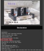
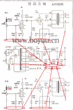
An example in the photo for you, so that you understand where the voltage comes from.
Yamaha CD-S2100 Output Level 2 +/- 0.3 V
Boyuu A9 Input Sensitivity: 750MV
if you feed amplifier 2v to the first stage (6N9PJ) of the amplifier, you get an overload, you get a bunch of distortion at the output of the amplifier.
The amplifier requires 750 mV, it requires a divider.
Attachments
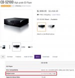
I don't doubt what you have said and shown from the specs.An example in the photo for you, so that you understand where the voltage comes from.
Yamaha CD-S2100 Output Level 2 +/- 0.3 V
Boyuu A9 Input Sensitivity: 750MV
if you feed amplifier 2v to the first stage (6N9PJ) of the amplifier, you get an overload, you get a bunch of distortion at the output of the amplifier.
The amplifier requires 750 mV, it requires a divider.
It's just that I don't understand how the 750mV 'sensitivity' number is calculated-or found by testing the amplifier.
The volume pot is a voltage divider - is the added divider with fixed resistors necessary?
Boyuu A9 Input Sensitivity: 750MV
if you feed amplifier 2v to the first stage (6N9PJ) of the amplifier, you get an overload, you get a bunch of distortion at the output of the amplifier.
The amplifier requires 750 mV, it requires a divider.
The amplifier requires 750mV to reach full output. With a volume pot, you reduce to input voltage to the first tube, therefore controlling the power output. Why do you need a voltage divider?
jeff
You are mistaken, 750mV constant. Colleagues with good English will explain why you need to coordinate the signal from the source to the amplifier.The amplifier requires 750mV to reach full output. With a volume pot, you reduce to input voltage to the first tube, therefore controlling the power output. Why do you need a voltage divider?
It is best to use for this matching transformer, less troublesome voltage divider.
"Matching transformers are designed to change the voltage level of electrical signals carrying useful information. They allow you to match the source of the signal with the load with minimal losses and minimal signal distortion."
Attachments
Question for Gregas:
When you notice the harshness in the sound at higher volumes, what's the position of the Volume control? 12 o'clock? 3 o'clock? 'wide open'?
It depends where you tighten the set screw for volume
Off. Is that normally at 6pm?
Anyhow it starts to distort around 75 percent open .
The output level of your device (player, DAC, etc.), you can find out in the specifications of this device. Calculate it is not necessary.I don't doubt what you have said and shown from the specs.
It's just that I don't understand how the 750mV 'sensitivity' number is calculated-or found by testing the amplifier.
The volume pot is a voltage divider - is the added divider with fixed resistors necessary?
Divider (resistors) is required. In some devices, the output signal can be up to 3v. C1 Mono D/A controller
It all depends on the output of your signal source. The volume control is only partially a divider, to a certain signal level.Anyhow it starts to distort around 75 percent open .
It all depends on the output of your signal source. The volume control is only partially a divider, to a certain signal level.
It is a voltage divider all the way, from zero to maximum. It is how it works.
how it works I know))It is a voltage divider all the way, from zero to maximum. It is how it works.
It seems to me that you did not encounter devices with a 2-2.5 V output, it is simply impossible to listen at 30% volume. Breeze Audio DAC SU3 high level Audio decoder ESS9018 XMOS Asynchronous USB DAC
Last edited:
Yes, you are correct about the position of the volume pot..It depends where you tighten the set screw for volume
Off. Is that normally at 6pm?
Anyhow it starts to distort around 75 percent open .
Most of the gear I have, 'Zero' is at about 7 o'clock and 'wide open' is at about 5 o'clock (clockwise rotation to increase).
That doesn't work for multi-turn pots or rotary digital encoders, I know!
When you get your hands on a scope and a few other bits of test gear, it will be interesting to look at the waveforms as the input voltage is increased, to see if you are getting clipping at higher input volumes.
Having 'efficient' speakers makes it easier when using relatively low-powered SE tube amplifiers. I didn't look up the specs on your speakers.
These are the speakers. I've got my volume knob set up pretty much like you've described. It sounds good at 12 noon then starts to get harsh and sometimes distort. Depending on the recording.
Monitor 7 v4 Specifications
Design - 3-driver, 2-1/2 way bass reflex, quasi- 3rd-order resistive port, floorstanding / tower
Crossover - 3rd-order electro - acoustic at 2.0kHz 2nd order electro - acoustic at 400Hz (lower bass driver)
Frequency Response - +/- 2dB from 47 Hz - 20 kHz
Low Frequency Extension - 33 Hz (DIN)
Sensitivity - 93 dB
Impedance - Compatible with 8 ohms
Maximum Input Power - 130 watts
Finish - Black Ash
Weight - 76 lbs. (34.5 kg)
Dimensions HxWxD - 40" x 7.625" x 15.375"
see(pic)
pick up a pass capacitor 102 202
Humble Homemade Hifi - Cap Test
be sure to match the input signal to the 750 mV amplifier
Voltage Divider Calculator
The Model A10 is not my amp (for some reason A10 schematics keep getting injected into this A9 thread discussion) - Mine is the Model A9 as per the schematics I uploaded in post #697. I think the A10 and A9 are different beasts are they not? Also mine has a PCB so it is not all P2P wiring as the schematics allude to which I think is why some of these discussions are confusing to me....
Last edited:
It seems to me that you did not encounter devices with a 2-2.5 V output, it is simply impossible to listen at 30% volume.
All you're doing is attenuating the input signal, so that your volume control has a normal range. I understand now why you're doing this, but you make it sound like a mandatory modification, which it's not.
I think the A10 and A9 are different beasts are they not? Also mine has a PCB so it is not all P2P wiring as the schematics allude to which I think is why some of these discussions are confusing to me....
The A10 has 6N2P input tubes, and all tubes appear to be PCB mounted, but the basic topology is the same.
jeff
Last edited:
With a different amplifier (with tone controls and 'loudness' bypassed or set 'flat') and the same music and same volume level (sound intensity from the speakers), do you find the same harshness problem?These are the speakers. I've got my volume knob set up pretty much like you've described. It sounds good at 12 noon then starts to get harsh and sometimes distort. Depending on the recording.
Your speakers are sensitive enough that you should be able to get the music fairly loud (but undistorted) with the A9...how big is your listening space ?
(And how close your neighbours?
)The schematic would be the same whether the amp was built P2P, with eyelet/turret board, or with a PCB.Also mine has a PCB so it is not all P2P wiring as the schematics allude to which I think is why some of these discussions are confusing to me....
It's baffling at first but with more time spent comparing the schematic with 'the real thing' on your bench, you will get more familiar with it.
Printing out the schematics for the A9 and A10 and looking at them side-by-side will show you that they are very similar.
The caps that LongRoad is suggesting for possible replacement are the coupling caps (.22 or .33 uF) between the 'preamp' tubes and the power tubes. They pass the AC signal but block DC. Changes like that can sometimes make subtle differences in amps that are already working well.
With a different amplifier (with tone controls and 'loudness' bypassed or set 'flat') and the same music and same volume level (sound intensity from the speakers), do you find the same harshness problem?
Your speakers are sensitive enough that you should be able to get the music fairly loud (but undistorted) with the A9...how big is your listening space ?
(And how close your neighbours?
There's definitely a difference. My solid state amp sounds Warmer. I can crank it up and no distortion. I just compared the same song. On the boyuu the female singer started to sound garbled. I played it on my other amp with flat response. No distortion in the voice at the same volume level.
Well, definitely time for the scope, then...
You've checked all the wiring for errors, the hum is low, swapped out tubes, so you have eliminated quite a few possibilities.
Having a close look for bad solder joints ('cold solder joints') and touching up any that look suspect would be one thing I'd do. Clean up with flux remover or isopropyl alcohol if necessary then re-solder where warranted. A flux pen, good solder, and a hot iron...you probably already have those, so you could pass some time while waiting for that scope.. Common Soldering Problems | Adafruit Guide To Excellent Soldering | Adafruit Learning System
You understood correctly. So the volume control works in full you need to lower the input signal to the specified value in the characteristics of the amplifier. As a voltage divider, you can use the volume adjustment potentiometer.All you're doing is attenuating the input signal, so that your volume control has a normal range. I understand now why you're doing this, but you make it sound like a mandatory modification, which it's not.
Using a calculator, you can consider the volume control as a resistor divider. As a result, we get the value of R101 and R201 see the scheme. Breeze Audio DAC SU3 high level Audio decoder ESS9018 XMOS Asynchronous USB DAC
Attachments
Last edited:
- Home
- Amplifiers
- Tubes / Valves
- Boyuu EL34 A9 Tube Amp