There isn't much wiggle room if the device need more than just 3 watts.
The chip amp is good for quite a bit more (see data sheet), the power supply determines the maximum output.
Transistor conduction losses are high when they operate below saturation. For much of the cycle of the sinewave, the output transistors of the amp will be operating below saturation. thus causing significant power loss.
Just stop thinking "SMPS". Think "Class B linear power amplifier". You don't saturate your transistors in these, just like in linear regulators. And yes, you have losses - 30% minimum, some 50% in our case here - but at some 5W, not 500, so it won't matter too much. Of course, regulator and amp need a small heatsink or chassis.
this is some sort of deathmatch challege
Oh no - do post your opinion; just read up on the previous discussion before throwing in some generic statements that are true but not very relevant here, OK?
[/B][/QUOTE]
I finished the entire circuit yesterday. The amp and regulator got really hot under no load - nothing blew though. I did manage to get the motor running, but it seemed to stutter a bit. After analyzing the wave form I noticed some distortion. I'm not sure whats going on, I ran out of time. I will have pics including the waveforms later on tonight hopefully.
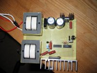
Here is the top and bottom. Don't bash too hard, this is my first 100% scratch build.
Raw rectified voltage is 16.5V, after voltage regulator 11.74V.
No dectible ripple present, Pure DC.
Tracing the signal...
3.200Khz right on the money.
Filtering and Counting...
Signal to be amplified (a little small at 54mV) - have to work on preamp stage
And the major problems...
At the trans primary (amp output) the voltage is ~4.56Vac (should be 6 roughly) and at the secondary, I'm only getting 123Vac...
Here is what my osc. shows. Excuse the blurryness, its an old fluke storage osc.
An externally hosted image should be here but it was not working when we last tested it.
An externally hosted image should be here but it was not working when we last tested it.
Raw rectified voltage is 16.5V, after voltage regulator 11.74V.
No dectible ripple present, Pure DC.
Tracing the signal...
3.200Khz right on the money.
An externally hosted image should be here but it was not working when we last tested it.
Filtering and Counting...
An externally hosted image should be here but it was not working when we last tested it.
An externally hosted image should be here but it was not working when we last tested it.
An externally hosted image should be here but it was not working when we last tested it.
Signal to be amplified (a little small at 54mV) - have to work on preamp stage
An externally hosted image should be here but it was not working when we last tested it.
And the major problems...
At the trans primary (amp output) the voltage is ~4.56Vac (should be 6 roughly) and at the secondary, I'm only getting 123Vac...
Here is what my osc. shows. Excuse the blurryness, its an old fluke storage osc.
An externally hosted image should be here but it was not working when we last tested it.
An externally hosted image should be here but it was not working when we last tested it.
An externally hosted image should be here but it was not working when we last tested it.
Success (partial). The motor is starting up and spinning correctly. I changed the preamp bipolar to a "C945" that I pulled off of an old computer speaker amp - MUCH less distortion. I also connected the amp directly to the power supply. I believe it is picking up emf from the transformer though, because I still see some sort of distortion but no where near as bad as before. I believe I may still need another intermediate gain stage.
I put a bigger heatsink, but I guess it wasn't enough... I have no gain from the amp anymore I think I over-heated and blew the amp  preamp stages are all fine. Can anyone suggest a heatsink good enough for this amp? One that will bolt directly on, I'm having trouble finding one. Also, I don't know why but the amp was heating up without any load - just the transformer connected and not the motor. Maybe there is something wrong with my circuit? I wasn't reading anything funny other than those distortions.
Rpapps, it was working fine earlier just not enough input, need more gain. See this configuration: You don't have to run 2x11W, you can turn it into a Bridge Tied Load and get 1x22W, this diagram should be clear.
preamp stages are all fine. Can anyone suggest a heatsink good enough for this amp? One that will bolt directly on, I'm having trouble finding one. Also, I don't know why but the amp was heating up without any load - just the transformer connected and not the motor. Maybe there is something wrong with my circuit? I wasn't reading anything funny other than those distortions.Rpapps, it was working fine earlier just not enough input, need more gain. See this configuration: You don't have to run 2x11W, you can turn it into a Bridge Tied Load and get 1x22W, this diagram should be clear.
An externally hosted image should be here but it was not working when we last tested it.
I tried the bipolar cap, no luck the amp wouldn't put anything through the primary.
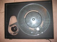
I have added bigger heat sinks, bought 2 new chip amps and rewired everything. The turntable is running now, I can't tell if the speed is correct. The scope is showing a DC offset problem (waveform is jumping around, not stable) and this amp still runs really hot, any idea where I can get a bigger, but similar heat sink? Other than that its running fine. I think I was putting 6.4Vac into the primary, and 190Vac or so out of the secondary according to my Fluke.
I have added bigger heat sinks, bought 2 new chip amps and rewired everything. The turntable is running now, I can't tell if the speed is correct. The scope is showing a DC offset problem (waveform is jumping around, not stable) and this amp still runs really hot, any idea where I can get a bigger, but similar heat sink? Other than that its running fine. I think I was putting 6.4Vac into the primary, and 190Vac or so out of the secondary according to my Fluke.
Attachments
- Status
- This old topic is closed. If you want to reopen this topic, contact a moderator using the "Report Post" button.
- Home
- Amplifiers
- Power Supplies
- Boost converter w/ Frequency Change