You don't need to upgrade past the notch filter. The fet opamps are not easy to swap since there are some tricks around them use an ad797 on the input board for the difference amp.
The caps do degrade and changing/ removing them help. I'll try to provide some easy tricks. There will be bigger improvements soon if all goes well.
Sent from my SGH-M919 using Tapatalk
The caps do degrade and changing/ removing them help. I'll try to provide some easy tricks. There will be bigger improvements soon if all goes well.
Sent from my SGH-M919 using Tapatalk
Alright, got it working again. The problem was caused by the oscillator board not being properly seated. This may sound like a silly mistake, but my 1121 took a harsh beating during shipping and is all bent out of shape, thus the boards don't line up as nicely as before.
I did some rudimentary adjustments (notch balance and tune, input CMRR) and so far it looks like the effort was worth it. I'll pull some numbers tomorrow and also post some pics")
I did some rudimentary adjustments (notch balance and tune, input CMRR) and so far it looks like the effort was worth it. I'll pull some numbers tomorrow and also post some pics
Finally got the 1121 working again!
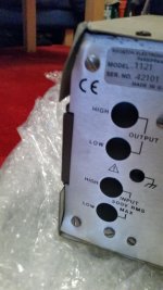
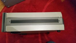
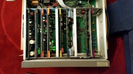
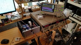
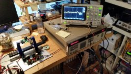
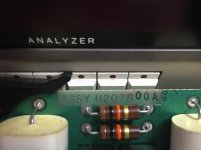
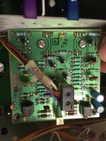
The first two pictures show how badly beaten up the 1121 got during shipping. The third picture was taken after doing the mods, but before straightening out the chassis. The unit wasn't reliably working because the frame was so bent out of shape that the daughter boards wouldn't properly contact the sockets. So I decided to completely disassemble the 1121, bent every single piece back into shape and then reassemble it again, hoping it would cure the issues. And it did
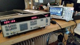
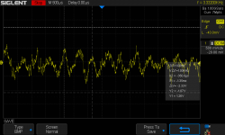
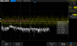
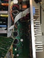
The fourth picture shows the 1121 operating in its unaltered state. The scope is connected to the monitor output, a screendump of which is shown in the 5th picture, along with an FFT in the 6th picture.
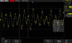
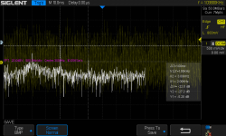
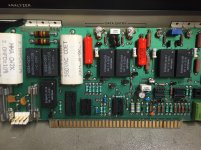
The 7th pic shows the 1121 operating in its modded state, after straightening out the chassis. All electrolytic caps were replaced with new ones, all coupling caps were replaced with non-polar ones and all the NE5534/32 were replaced with LME49710/20 (see post #80). I also reduced R52 and R54 from 10 ohms to 2 ohms, as was suggested in post #33. The monitor output and an FFT thereof are shown in the 8th and 9th picture. Scaling and settings are identical between the oscilloscope pics. The improvements can be clearly seen. Distortion is still mostly 2nd harmonic.
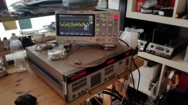
And finally, the last (10th) pic is showing the 1121 in action. I used it to set the AC current gain of my Aleph Headphone amp (see http://www.diyaudio.com/forums/pass-labs/244954-aleph-h-schematic-revealed-last-3.html#post4351290) for minimum distortion. The yellow trace is the output signal of the 1121, and the violet (magenta?) trace is the monitor output of the 1121 with the amp's output connected to the 1121's input.
I noticed some 50/100Hz modulation of the monitor output for small signal levels, as can also be seen in the last pic. Any input/suggestions on that?
The first two pictures show how badly beaten up the 1121 got during shipping. The third picture was taken after doing the mods, but before straightening out the chassis. The unit wasn't reliably working because the frame was so bent out of shape that the daughter boards wouldn't properly contact the sockets. So I decided to completely disassemble the 1121, bent every single piece back into shape and then reassemble it again, hoping it would cure the issues. And it did
The fourth picture shows the 1121 operating in its unaltered state. The scope is connected to the monitor output, a screendump of which is shown in the 5th picture, along with an FFT in the 6th picture.
The 7th pic shows the 1121 operating in its modded state, after straightening out the chassis. All electrolytic caps were replaced with new ones, all coupling caps were replaced with non-polar ones and all the NE5534/32 were replaced with LME49710/20 (see post #80). I also reduced R52 and R54 from 10 ohms to 2 ohms, as was suggested in post #33. The monitor output and an FFT thereof are shown in the 8th and 9th picture. Scaling and settings are identical between the oscilloscope pics. The improvements can be clearly seen. Distortion is still mostly 2nd harmonic.
And finally, the last (10th) pic is showing the 1121 in action. I used it to set the AC current gain of my Aleph Headphone amp (see http://www.diyaudio.com/forums/pass-labs/244954-aleph-h-schematic-revealed-last-3.html#post4351290) for minimum distortion. The yellow trace is the output signal of the 1121, and the violet (magenta?) trace is the monitor output of the 1121 with the amp's output connected to the 1121's input.
I noticed some 50/100Hz modulation of the monitor output for small signal levels, as can also be seen in the last pic. Any input/suggestions on that?
Attachments
-
 IMG_20160125_172055.jpg303.3 KB · Views: 339
 -
 IMG_20160125_173610.jpg932.5 KB · Views: 308
 -
 IMG_20160218_190618.jpg1,019.2 KB · Views: 315
 -
 IMG_20160131_203515.jpg1,022 KB · Views: 317
 -
 before_monitor.png37.1 KB · Views: 292
 -
 before_FFT.png74.8 KB · Views: 159
 -
 IMG_20160228_114252.jpg887.2 KB · Views: 170
 -
 after_monitor.png31.9 KB · Views: 166
 -
 after_FFT.png60.7 KB · Views: 137
 -
 IMG_20160228_094504.jpg997.8 KB · Views: 179
Last weekend I put together a crude setup with Victor's Ultra Low Distortion Oscillator (1kHz version) to check the lower limit of the distortion analyzer. The detector section is going down to about 0.0006% with Victor's oscillator. Sweet.
Try making a jig for Victor's oscillator using male panel mount male BNC on the board -- and 9V alkaline cells for power, with very short cables.
I don't think you will get much better than the .0006% number. Two issues will loimit it. First the noise at the input which while low would need the 10K series protection resistors R13 and R14 to be lower, but that brings risk of overload frying parts. Light bulbs will work if you can find the right 220V lamps (3W I think). Second limitation is the analog multipliers. (Third is the FET attenuator switches etc.)
Still .0006% or -104 dB is very good. And the voltage accuracy for botht he analyzer and the generator is quite high.
Did you put in the jumpers and remove the TL072 opamps on the input board?
Still .0006% or -104 dB is very good. And the voltage accuracy for botht he analyzer and the generator is quite high.
Did you put in the jumpers and remove the TL072 opamps on the input board?
To answer your question, 1audio, no, I have yet to jumper the TL072 opamap on the input board. I'll have to read through the thread again I guess. And I've been looking for 220V/3W bulbs, they're surprisingly hard to find. Here's one specimen of these so called "Kleinröhrenlampen": https://www.conrad.de/de/kleinroehr...kele10-klar-barthelme-inhalt-1-st-582826.html If anyone is interested, I could get a couple and mail it to you guys, sort of like a mini GB.
And I have question:
Does anyone know how the phase of the residual distortion signal from the monitor output relates to the signal fed into the 1121's input? Any guesses perhaps?
Edit: I guess the phase relation could be easily determined empirically by deliberately worsening the nulling of the fundamental and then comparing the monitor output with the analyzer's input?
Last edited:
1120/ S10
Anybody got schematics for the output amp on a S10? I also need schematic on a input board no 1120 117800A. Something is loading the 5V line down to 2,8V, and as you can proably imagine, Error 34-33-31 and all that nuisance.
The source works just fine when the input board is pulled.
Thanks
Roar
Anybody got schematics for the output amp on a S10? I also need schematic on a input board no 1120 117800A. Something is loading the 5V line down to 2,8V, and as you can proably imagine, Error 34-33-31 and all that nuisance.
The source works just fine when the input board is pulled.
Thanks
Roar
Attachments
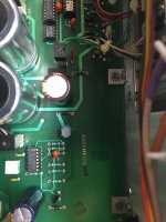
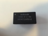
Its listed in both the 1120 and 1121 manual as a 15V pseudo form C reed relay, part number Wabash 1632-3-1 which seems to be a dead end. Later units have an identical relay labeled Coto. Functionally K9 is a single form C relay and it seems a Coto 7141 12V relay would fit and work in that location. Here is a link to a datasheet http://cotorelay.com/wp-content/uploads/2014/09/7000_series_reed_relay_datasheet.pdf Digikey has what seems to be the wrong version: 7141-12-1011 Coto Technology | Relays | DigiKey I think the desired part would be 7141-12-11XX but i need someone else checking. If bending leads is an OK option then more alternatives exist- 12V spdt relay . The coil is top to bottom. Check the PCB layout for the contact arrangement but it is based on reed relays so they are straight across.
At the price they are asking vs. cost of the relays alone its worth doing. There are a few small changes between models.
Another immediate fix would be to pull K3 and install for K9. K3 just shorts the neg input and causes more problems than it helps. Just short the neg input externally for single ended input at the DUT, lower noise anyway. I have replaced fuses too often and fried 2 of the K3 relays.
Another immediate fix would be to pull K3 and install for K9. K3 just shorts the neg input and causes more problems than it helps. Just short the neg input externally for single ended input at the DUT, lower noise anyway. I have replaced fuses too often and fried 2 of the K3 relays.
- Home
- Design & Build
- Equipment & Tools
- Boonton 1120/1121 Distortion Analyzer tweaks