Update on Boonton 1121 residual distorton progress
I know it has been a while, but I am really starting to peel the onion to find the lowest residual distortion for the Boonton 1121. My latest modifications have dropped the noise and distortion even further. See picture with spectrum graph...
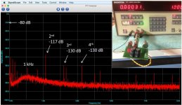
My original 1120/1121 design used 3V rms for the full scale amplitude through the analyzer section. I found that the Notch Filter Board worked better at lower levels than 3 V while the rest of the analyzer amplifier chain had better S/N while operating at higher levels. It took a little work but the analyzer is now running at 6V rms full-scale, improving the noise floor while at the same time, the notch filter is running at around 2 V. I am continuing to test to see if the unit meets all specifications after these modifications. I also tried these modificaitons on two notch boards and they both have similar results. All 5534s and 5532s have been removed and replaced with LME49710s and 20s. The FFT plot is connected to the Monitor output and there is 80 dB of gain after the notch filter at -10 dB reference level on the FFT analyzer so -10 dB is really -80 dB below the fundamental. The THD+N reading is measuring primarily power line components and the second harmonic residual. With the power line components removed, the display would be 0.00025%. Once I am satisfied that the modifications do no harm, I will post them. I need to continue to work on the nulling of the fundamental. At these levels, I am not satisfied that the fundamental rejection is good enough. I will post more as I make progress.
I know it has been a while, but I am really starting to peel the onion to find the lowest residual distortion for the Boonton 1121. My latest modifications have dropped the noise and distortion even further. See picture with spectrum graph...
My original 1120/1121 design used 3V rms for the full scale amplitude through the analyzer section. I found that the Notch Filter Board worked better at lower levels than 3 V while the rest of the analyzer amplifier chain had better S/N while operating at higher levels. It took a little work but the analyzer is now running at 6V rms full-scale, improving the noise floor while at the same time, the notch filter is running at around 2 V. I am continuing to test to see if the unit meets all specifications after these modifications. I also tried these modificaitons on two notch boards and they both have similar results. All 5534s and 5532s have been removed and replaced with LME49710s and 20s. The FFT plot is connected to the Monitor output and there is 80 dB of gain after the notch filter at -10 dB reference level on the FFT analyzer so -10 dB is really -80 dB below the fundamental. The THD+N reading is measuring primarily power line components and the second harmonic residual. With the power line components removed, the display would be 0.00025%. Once I am satisfied that the modifications do no harm, I will post them. I need to continue to work on the nulling of the fundamental. At these levels, I am not satisfied that the fundamental rejection is good enough. I will post more as I make progress.
Attachments
I know it has been a while, but I am really starting to peel the onion to find the lowest residual distortion for the Boonton 1121. My latest modifications have dropped the noise and distortion even further.
.... the display would be 0.00025%. Once I am satisfied that the modifications do no harm, I will post them. I need to continue to work on the nulling of the fundamental. At these levels, I am not satisfied that the fundamental rejection is good enough. I will post more as I make progress.
very nice progress and improvements

THx-RNMarsh
Last edited:
Hi. My Boonton 1120 analyzer reads voltages incorrectly. It reads all voltages in the mv scale- in mv's the value displayed reads wrong, but strangely, the voltage numerals appear correct. What is the fix? Thanks.
So the numbers are correct? Only the units indicators are wrong? Is is ALWAYS showing mV, never V?
jan
Hi. My Boonton 1120 analyzer reads voltages incorrectly. It reads all voltages in the mv scale- in mv's the value displayed reads wrong, but strangely, the voltage numerals appear correct. What is the fix? Thanks.
I am sure we can work this out. The fact that the number appears right and the units are wrong is likely a coincidence. The first thing I would do is make sure that the source is generating the right level at 1 kHz. Assuming this is correct, I would make sure that the input fuses are not blown on the input board. There are two, one for the Hi input and one for the Lo input. One thing that can cause this to happen is one or more AC level ranges may be at fault. There are a number of special functions described in the manual that can test to see if there is a problem on a particular AC level range. Do you have a copy of the manual? They are special functions 32, 33 and 34. The use of these special functions is described in section 5 under Troubleshooting.
What AC voltages have you tried? Can you provide more details? I would be happy to help you walk through troubleshooting. Let me know what test equipment you have (oscilloscope, voltmeter, etc.) that you can use to troubleshoot the 1120.
Thanks,
Mike
Hello,
I picked up an 1120 at my local surplus shop a couple months ago. Quite a nice machine. I hope to follow along with the mods in this thread, and hopefully make some contributions at some point.
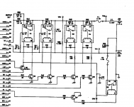
First, I want to fix some problems I'm having when using the output in 'float' mode. I have the newer model 1120, with the power amp at the back of the unit, it matches this 1121 schematic (page 7-27, pdf page 173):
http://boonton.com/~/media/Boonton/Manuals and Software/1121 Instruction Manual.ashx
My question is: Why doesn't the LOW amplifier output pass through the relay attenuators / impedance selectors, the same as the HIGH output?
Also, C23 seems a bit large, and I'm surprised that the amplifier output is shorted directly to ground when running singled-ended. Am I missing something here?
If I want true balanced output, should I construct a second card with this attenuation circuit for the LOW output?
I picked up an 1120 at my local surplus shop a couple months ago. Quite a nice machine. I hope to follow along with the mods in this thread, and hopefully make some contributions at some point.
First, I want to fix some problems I'm having when using the output in 'float' mode. I have the newer model 1120, with the power amp at the back of the unit, it matches this 1121 schematic (page 7-27, pdf page 173):
http://boonton.com/~/media/Boonton/Manuals and Software/1121 Instruction Manual.ashx
My question is: Why doesn't the LOW amplifier output pass through the relay attenuators / impedance selectors, the same as the HIGH output?
Also, C23 seems a bit large, and I'm surprised that the amplifier output is shorted directly to ground when running singled-ended. Am I missing something here?
If I want true balanced output, should I construct a second card with this attenuation circuit for the LOW output?
Attachments
Its not obvious at first but the whole generator circuit from power supply to output connectors is floating and either the - output is connected to ground for single ended or left floating for balanced. In the cal doc there is a test for confirming the isolation of the outputs.
The biggest issue I have with the Boontons is that on reset the - connections are shorted to ground. More than a few times the inadvertent reset left me opening the box to replace the fuses.
For most measurements you should float both in and out and tie the chassis of the Boonton to the DUT ground with a separate cable. This will have the lowest noise.
Wondering about early or late type unit serial number is #11401DB ?
BTW, anyone familiar with Roger Rosens' distortion reduction idea for phase shift oscillators?
It mainly reduces 3rd:
http://www.keith-snook.info/wireles.../Phase-shifting oscillator - Roger Rosens.pdf
BTW, anyone familiar with Roger Rosens' distortion reduction idea for phase shift oscillators?
It mainly reduces 3rd:
http://www.keith-snook.info/wireles.../Phase-shifting oscillator - Roger Rosens.pdf
The differences are not big and most of the changes can be implemented on any unit.
The early 1120 does not have a heat sink on the back and max output of the oscillator is 3V think. Later ones and 1121 are 16V out.
I'll look at that oscillator trick soon.
Sent from my SGH-M919 using Tapatalk
The early 1120 does not have a heat sink on the back and max output of the oscillator is 3V think. Later ones and 1121 are 16V out.
I'll look at that oscillator trick soon.
Sent from my SGH-M919 using Tapatalk
I was going to try some of the upgrades mentioned in this thread. They are great suggestions! I found out my 1120 has a different notch board than the one in the manual that I have for the 1120. The notch board serial number is 112017 00A/D. My unit serial number is 16101DA with 13-15 options. Instead of the Harris HA3 op amp, it has a NE5532AN and a few other parts changes. Does anyone have a schematic for this board? The other boards in the unit appear to better match the manual that I have. Any help is appreciated!
It is in the place of the Harris HA3 (U10) on the notch board. The input tantalum capacitors were also different values. They are 56uf (this was the same) and 15uf (different). The diodes associated with U10 were also missing. The board is marked 112017 00A/D. Let me know if you have the schematic. Thanks!
U10 is a buffer that drives the phase and amplitude notching circuits. The cap values need to be large enough to pass 10 Hz without phase shift. DC offset will cause some issues in nulling so there is some careful balancing. The Harris is a really wideband uncompensated opamp which may help with the nulling. Its listed as having a min gain of 5, 100 MHz GBW and .5 mV of offset, all very good. Still available from Intersil. Its not in the distortion path. There are some alternates that can do the same. The oldest manual I have shows it as an HA-2625.
I should be getting a 1121 model next week and have read through this thread with great interest. I'm already looking forward to giving the device a nice overhaul, albeit it's supposed to be in good condition.
A question: Is there a higher quality version of the manual/schematics available? I've found a 3MB pdf version online, but some of the part numbers and values are hard to read.
A question: Is there a higher quality version of the manual/schematics available? I've found a 3MB pdf version online, but some of the part numbers and values are hard to read.
Well, upon further inspection of the manual I realized that the component values are conveniently listed in tables...
I'm now about to replace all electrolytic PSU filter/decoupling caps with new ones (CDE SLPX and Panasonic FR) and also all polar coupling caps with non polar ones (Nichicon Muse ES).
I'm also replacing all the NE5534/32 with LME49710/20, except for the one or two positions where a FET-input opamp is called for.
I'll post a summary and results of the mods once I've verified that the 1121 is still working .
Lastly, I've got a question concerning the CMRR adjustment: The manual is mentioning a Wave Analyzer that is to be connected to the Monitor output. Can I do the CMRR adjustment with an oscilloscope instead?
Attachments
- Home
- Design & Build
- Equipment & Tools
- Boonton 1120/1121 Distortion Analyzer tweaks