Hi Bob,
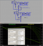
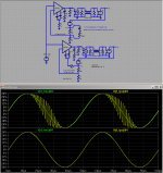
To put it more 'real' your assertions, I have done 2 simms. that shows the case. Both amps are the same (my design topology), without the LP input filter, signal DC coupled, the only difference is that one the 'unstable' runs without my compensation scheme (the values of the amp are slightly different from the original with a degeneration of 6.8R {enough low to show the truth of your assertion}). I've put a 'resonating load' at about 3MHZ to trigger the unstable condition (overshot while clipping is the resonance of the load itself). I've feed both amps with the same 'music material' at a rather high frequency (100KHZ), but it doesn't has importance (can be scaled to any freq.). So the input is asynchronous and has different levels of amplitude from low, medium, high, soft and hard clipping levels. Your suspicions are quite REAL as both amps are APPARENTLY reproducing the same 'music' while the unstable amp is oscillating at 20MHZ and music is modulating the oscillation showed in the first pix (RED,PINK,PALE YELLOW,PALE VIOLET traces at VAS input). Now with my compensation scheme (C5=C6=680pf) the stable reproduction in the second pix with the same 'resonating' load. I could say that this compensation scheme works pretty good as it not degrade slew nor distortion to any extent, I am very amused with this results. The third pix show FFT at 1KHZ 31 Watts RMS output of the compensated version.
Cheers
Arturo
Hi Arturo,
This is a nice comparison. It does indeed look like your capacitors are stabilizing the amplifier. It also looks like the unstable amplifier is more or less oscillating all of the time except when clipping. Is that correct?
Cheers,
Bob
Hi, Bob,
This example was to show a high frequency instability, that why I used a small degeneration, to stimulate the high freq. oscillation upraise, make it dominant, and not let the oscillation of the load be the dominant one. If I understood correctly it was the point (among others) you made about the "misleading behaviour of some amps bursting trains of high freq. oscillations apparently working ok". Yes, during clipping the 'unstable' amp resets oscillation at the seed frequency and is capable to dump it to a level that doesn't dominate the high freq. instability when re-enters the linear region, a very tricky situation, but it is an example of one case among all foreseeable cases. That's why with this compensation scheme, I believe it would be possible to degenerate it below the 'traditional minimum safe margins', obtaining a stable lower distortion amp.
Cheers
Arturo
I went back and soldered it up again:
Edcor 8K into Cordell Load:
An externally hosted image should be here but it was not working when we last tested it.
Edcor with Infinity Kappa6
An externally hosted image should be here but it was not working when we last tested it.
Fisher400 with Cordell Load:
An externally hosted image should be here but it was not working when we last tested it.
Hi Jack,
Interesting plots. I'm not familiar with the Edcor transformer. Can you say a few words about it?
Also, can you say a bit more about what conclusions you have drawn?
BTW, one of these days I want to come up with a simulation load for a 3-way system that has some impedance peaks and dips at the crossover frequencies.
Cheers,
Bob
The Edcor transformer is used by Pete Millett in the "Engineers Amplifier" -- 8K Primary. DCPP Amp.
My conclusion is that the schematic mirrors reality pretty neatly. (Sorry for the earlier post which had a soldering malhappenstance.) Certainly nice to have something you can put on the bench without the fear that instability or DC offset is going to blow-up a $100 driver. Next step, however, would be to replace the 6.4R and 15R (R1, R2) resistors with higher power varieties.
My conclusion is that the schematic mirrors reality pretty neatly. (Sorry for the earlier post which had a soldering malhappenstance.) Certainly nice to have something you can put on the bench without the fear that instability or DC offset is going to blow-up a $100 driver. Next step, however, would be to replace the 6.4R and 15R (R1, R2) resistors with higher power varieties.
The Edcor transformer is used by Pete Millett in the "Engineers Amplifier" -- 8K Primary. DCPP Amp.
My conclusion is that the schematic mirrors reality pretty neatly. (Sorry for the earlier post which had a soldering malhappenstance.) Certainly nice to have something you can put on the bench without the fear that instability or DC offset is going to blow-up a $100 driver. Next step, however, would be to replace the 6.4R and 15R (R1, R2) resistors with higher power varieties.
Thanks, Jack. I've long been fascinated with VT amplifiers, going back to my teen years in the 60's. Built quite a few back then; 6V6, EL34, 6550, etc. This looks like a fun writeup.
Cheers,
Bob
Hi, Bob,
This example was to show a high frequency instability, that why I used a small degeneration, to stimulate the high freq. oscillation upraise, make it dominant, and not let the oscillation of the load be the dominant one. If I understood correctly it was the point (among others) you made about the "misleading behaviour of some amps bursting trains of high freq. oscillations apparently working ok". Yes, during clipping the 'unstable' amp resets oscillation at the seed frequency and is capable to dump it to a level that doesn't dominate the high freq. instability when re-enters the linear region, a very tricky situation, but it is an example of one case among all foreseeable cases. That's why with this compensation scheme, I believe it would be possible to degenerate it below the 'traditional minimum safe margins', obtaining a stable lower distortion amp.
Cheers
Arturo
Hi Artu,
I think it is still important to review why we want to be able to have lower input stage degeneration in the first place. I don't think that is really the goal. Yes, it increases open-loop gain, all else remaining equal, but gain by itself is easily had in most amplifier architectures. The increased signal-handling ability and linearity afforded the input stage by degeneration is really important in decreasing distortion. It is also unnecessary to avoid input stage degeneration to achieve lower noise in an amplifier, because the noise is already low even when degeneration is used, and often other parts of the circuit may dominate noise, like the feedback network. There are many tradeoffs here, but I'm just noting that the ability to operate the input stage with less degeneration does not, by itself, seem to be a useful goal.
Cheers,
Bob
It is also unnecessary to avoid input stage degeneration to achieve lower noise in an amplifier, because the noise is already low even when degeneration is used, and often other parts of the circuit may dominate noise, like the feedback network.
I have often wondered why feedback networks use such high values of resistors. Is it to require a lesser value of feedback cap? What tradeoffs are made when lowering the feedback resistors?
I have often wondered why feedback networks use such high values of resistors. Is it to require a lesser value of feedback cap? What tradeoffs are made when lowering the feedback resistors?
Hi Pooge,
This is a good question.
There are many good reasons to use a low-impedance feedback network. It reduces resistor Johnson noise at the input and also reduces noise created by the input noise current of the bipolar input LTP transistors (one good argument for JFET LTP, BTW). A low-Z feedback network also acts to reduce excess phase lag due to the summing node pole formed between the FB network impedance and the input capacitance of the LTP. A bit of common-mode distortion at the LTP may be reduced as well.
There are some disadvantages to using a low-Z feedback network, however. One is the size of the conventional blocking capacitor in the shunt leg of the FB network. It gets pretty big if good low-frequency response is to be maintained with a small feedback network shunt resistance. Eliminating this problem is one of the good reasons for using a DC servo.
A low-Z feedback network also requires greater attention to the sizing of the feedback network resistors, especially in high-power amplifiers. Audio signal-dependent power dissipation in feedback resistors is very undesirable. A feedback network with a nice 250-ohm impedance, for example, might have a feedback resistor on the order of 5k. Power dissipation with 50 V rms across 5k will be about 0.5 watt. This can cause significant temperature variation in even a 2-watt resistor.
Finally, many amplifiers with balanced inputs require the use of a fairly Hi-Z feedback network to keep the input impedance on the inverting side (shunt feedback) to be a reasonable value that can be driven typically by a unity gain buffer stage with low distortion. A good example of this is the JC-1, where the feedback resistor is about 50k.
Cheers,
Bob
Hi Artu,
I think it is still important to review why we want to be able to have lower input stage degeneration in the first place. I don't think that is really the goal. Yes, it increases open-loop gain, all else remaining equal, but gain by itself is easily had in most amplifier architectures. The increased signal-handling ability and linearity afforded the input stage by degeneration is really important in decreasing distortion. It is also unnecessary to avoid input stage degeneration to achieve lower noise in an amplifier, because the noise is already low even when degeneration is used, and often other parts of the circuit may dominate noise, like the feedback network. There are many tradeoffs here, but I'm just noting that the ability to operate the input stage with less degeneration does not, by itself, seem to be a useful goal.
Cheers,
Bob
Hi Bob,
Yes you are right, I should say that it is a bad idea lowering too much the degeneration below PM of 60° (to put a value). Also degeneration 'linearises' Gm, it makes it less dependent on BJT internals. With my compensation scheme at the VAS (I should empathise this, and the topology and the components used, as I didn't verified with other topologies yet) PM can be lowered safely to as low as 34° !!! (I bet that most amp's oscillate with this value). Also distortion has a ceiling where the amp as a whole increments distortion as degeneration increases (OLG decreases and the FB network becomes 'suboptimal'), so there is a trade off between stability and distortion.
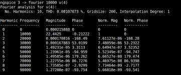
I show the results of distortion at 10KHZ 1V input for 2 stable amps.
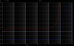
1) without compensation caps and 47R degeneration, PM=60° f180°=23.7MHZ pix 1 is THD and pix 2 is H1 H2 profile over audio BW, H1 ~= 33.5uV and H2 ~=97.7uV
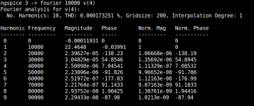
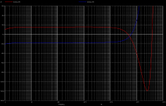
2) with compensation caps 680pf, 5.1R degeneration, PM=34° f180°=14.4MHZ pix 3 is THD and pix 4 is H1 H2 profile over audio BW, H1 ~= 15.5uV and H3 ~=17.7uV
The comparisons:
THD 2) is 6.1 times lower than 1)
H1 2) is a half of 1)
H2 2) is 5.5 times lower than 1)
So you may ask me, both levels of distortion 1) and 2) are inaudible so it worth all this stuff? and I am afraid that it maybe not worth, but I like the FFT profile of 2) because it lowers the same the even's and the odd's harmonics, if this thing works as I expect should be a killer amp, I am waiting the PCB to assemble it and begin the 'experiments' to see how 'close' or 'far' are the extensive simulations I've done, most probable I will end at 1).
I am sure that there is much more behind the scene than a simple LPF at 'loosed' leg of the diff. VAS that is a non-linear interaction between both emitters that splits oscillating energy out of resonance, it's my speculation a sort of 'mixing' process.
Cheers
Arturo
Curr ent Source
Hi Bob,
On page 36 of your book you start talking about current sources. The main point is the ability of the current source to keep supplying the same stable current within all kind of variations. Zout of the source is a big factor in the debate... Figure 2.10f on page 40 implies a feedback current source.
I used this source in what I built this far since I took the idea from the book of Randy Slone. When I look carefully at his designs he uses this source in conjunction with NON complementary designs. In the complementary ones he uses a current source biased with two 1N4148 diodes in series. I started wondering why?
Off-course there is the explanation he uses the feedback current source to ALSO set the current source for the VAS current source which is not usefull in the complementary design.
Or is it because the gain in quality by using this source is not going to improve the complementary design, so why bother the extra Q's?
Or is there some other reason?
Edmond ones replaced my proposition of the feedback CS with diode or zener biased source stating it would be faster or more capable of delivering current (I admit I have to check out again what he wrote exactly).
Do you think this type of source could generate HF problems like instability? RF oscillations? Extra poles in the bodeplot?
Maybe the ultra high Zout of these sources picks up RF more easily or they require a special PCB tracing approach?
Thnx
Olivier
Bob,
I have read most of your new book. I have tried to understand and learn as much information as this old brain can absorb.
Now do you think a newer book explaining to us what we should build instead of how to build may be next. All of the technical information can be tweaked to some extent and produce a fabulous amp or a mediocre one. These small details are what causes the most discussion here at DIY audio and on the net as a whole.
Now I know that this is a very unstable set of waters to tread in but, given the extend of your knowledge I know you have some really nice pet projects which you could let us layman construct. The building is where I get my enjoyment. The initial twist of the variac and not seeing any smoke is most enjoyable.
Any thoughts on this.
One last super amp for the masses. Something like a Dr. Cordell amp.
Tad
Cordell amp
Not that it was planned , but this thread and the Cordell "negative feedback" thread brought about my favorite amp. E. Staurt and his injection of TMC made the "sterile" Lin topology amp "come alive". My thread (the mongrel - AX) - http://www.diyaudio.com/forums/solid-state/169590-mongrel-supersym-ii-27.html#post2444212 , and The "ultra ULD extreme" thread - http://www.diyaudio.com/forums/solid-state/142166-new-amplifier-uld-extreme-9.html#post2444449 is where "the book hits the pavement". The new book absolutely helped to both confirm and facilitate a real stable , super low distortion , "killer amp". Besides another similar design ( the quasi amp) these 2 threads are the most present ones that deal with mr. Cordells main Lin topology example. We used to call it the "blameless" ... but now we have someone else to "blame".
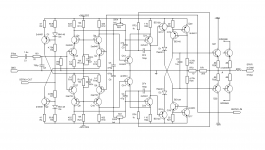
Bob's book made me do my 4'th and ...hopefully final , revision (below) , all decked out with a compensation "playground". -all the flavors (LC/TMC/TPC/CMC) ...
OS
Not that it was planned , but this thread and the Cordell "negative feedback" thread brought about my favorite amp. E. Staurt and his injection of TMC made the "sterile" Lin topology amp "come alive". My thread (the mongrel - AX) - http://www.diyaudio.com/forums/solid-state/169590-mongrel-supersym-ii-27.html#post2444212 , and The "ultra ULD extreme" thread - http://www.diyaudio.com/forums/solid-state/142166-new-amplifier-uld-extreme-9.html#post2444449 is where "the book hits the pavement". The new book absolutely helped to both confirm and facilitate a real stable , super low distortion , "killer amp". Besides another similar design ( the quasi amp) these 2 threads are the most present ones that deal with mr. Cordells main Lin topology example. We used to call it the "blameless" ... but now we have someone else to "blame".
Bob's book made me do my 4'th and ...hopefully final , revision (below) , all decked out with a compensation "playground".
-all the flavors (LC/TMC/TPC/CMC) ...OS
Attachments
I hope I’ve established that the only informative way to view the loop gain of TMC is by measuring “inside” both loops – ie the total gain around the output Q as illustrated in my added delay sim http://www.diyaudio.com/forums/soli...lls-power-amplifier-book-134.html#post2420438 and my following post below
This clearly shows the ~1.7 MHz gain intercept of TMC which agrees with some of the circuit analysis that have been presented – and the analysis show how a lead network can be added to a TPC amp to give equivalent loop gain intercept, phase margins
Bob posted a “comparison” of TPC vs TMC clipping behavior with some amp circuit modifications and an added bridging C across the T network of both TPC, TMC http://www.diyaudio.com/forums/solid-state/171159-bob-cordells-power-amplifier-book-137.html
I modded my BobAmp to match the clipping example amp circuit, with an added lead network for the TPC amp that gives a good match between the TPC, TMC loop gains (properly measured) as shown in the 1st plot – with the delay stepping to show that they remain equivalent over a range of output phase shift
I then added the extra load, upped the input level to match Bob's Clipping sim conditions and changed the step parameter to switch out the lead network – you can see that with the lead network, which gives good loop gain, phase margin match, the clipping behavior of TPC, TMC are essentially the same in the @1 step of the 2nd plot
my TPC example below without the lead network rings badly – even worse than Bob’s Clipping example because I left off the 0.5pF bridging C on both TPC, TMC sims - to show the superiority of the lead compensation approach
The only “fair” way to compare TPC, TMC is to match the total loop gain and phase around the output stage, this can be done with an added lead network for the TPC case
With the lead network TPC matches TMC clipping behavior, unlike in Bob’s sim
This clearly shows the ~1.7 MHz gain intercept of TMC which agrees with some of the circuit analysis that have been presented – and the analysis show how a lead network can be added to a TPC amp to give equivalent loop gain intercept, phase margins
Bob posted a “comparison” of TPC vs TMC clipping behavior with some amp circuit modifications and an added bridging C across the T network of both TPC, TMC http://www.diyaudio.com/forums/solid-state/171159-bob-cordells-power-amplifier-book-137.html
I claim the conditions are “unfair” in that example because the loop gain's phase margins are very different with very small phase margin for Bob’s example TPC circuit... It is easy to see that both TPC and TMC do not recover from clipping as well as CMC. However, TPC is much worse than TMC, getting into an oscillation that does not cease until the polarity of the signal changes unfair comparison - this TPC example has ~24 degrees phase margin vs 57 for the TMC Clip example, the gain intercept freq do match pretty well with the bridging C
(interestingly, the negative polarity is more stable, probably due to differences in the output transistors.
I believe the pos/neg difference is due to the VAS being completely cut off - 0 Ic on the positive clip
BTW, the TPC and TMC versions have about the same amount of distortion reduction, and the total feedback around the output stage in each has about the same phase and gain margins. (possibly an error reading the stacked cursor report boxes with multiple sims open? - they are not the same) Also, small-signal squarewave response shows about the same amount of ringing.
Overall, TMC and TPC give up some stability in reducing distortion as compared to CMC, so they have to be evaluated carefully both in small signal and large signal. They are both very worthwhile techniques, but like any tool, must be properly applied. It appears that large-signal behavior of TPC is significantly worse than that of TMC when margins are close. Overall, I still am inclined to prefer TMC over TPC. I claim wrong approach to matching = wrong conclusion
Cheers,
Bob
I modded my BobAmp to match the clipping example amp circuit, with an added lead network for the TPC amp that gives a good match between the TPC, TMC loop gains (properly measured) as shown in the 1st plot – with the delay stepping to show that they remain equivalent over a range of output phase shift
I then added the extra load, upped the input level to match Bob's Clipping sim conditions and changed the step parameter to switch out the lead network – you can see that with the lead network, which gives good loop gain, phase margin match, the clipping behavior of TPC, TMC are essentially the same in the @1 step of the 2nd plot
my TPC example below without the lead network rings badly – even worse than Bob’s Clipping example because I left off the 0.5pF bridging C on both TPC, TMC sims - to show the superiority of the lead compensation approach
The only “fair” way to compare TPC, TMC is to match the total loop gain and phase around the output stage, this can be done with an added lead network for the TPC case
With the lead network TPC matches TMC clipping behavior, unlike in Bob’s sim
Attachments
Last edited:
oops, I had my loop gain probe in the "wrong" position...
I messed up the TPC, TMC Clip measurements and ran out of edit time - they do have different loop gain curves with different unity gain intercept frequencies but the rest of Bob's comments are correct in that phase margins are similar (and low, < 30 degrees) and both show good gain margin
despite the slightly higher unity gain intercept both the lead network corrected TPC and TMC without the bridging C show similar gain and phase gain margins compared to Bob's Clip examples when both have the added output loading - decreasing loop intercept frequency to match Bob's Clip circuit's intercepts gives a clear win for the lead corrected version
I believe that the TPC with added feedback lead network is a more "natural" means to match the response of TPC, TMC - easier to see with the wye-delta transform
the clipping performance improvement is clear
the implied sensitivity to strays with the tiny 0.5 pF bridging C having such a large effect is a little scary for either approach
I might "spend" some of the greater loop gain of the TPC to cut the input degen some - allowing larger compensation C, lower Z and hopefully less stray sensitivity
AC guarding the VAS input node may be a good idea too
(note to self: double check before pressing "save")
Last edited:
My apologies to all
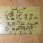
Hi, I am very sorry, my apologies to all, specially to Bob, but I did a GROSS error in the schematic of the circuit (it is a transcription of a .cir text file), I hope that nobody wasted time simulating the prior circuit (sightly changed), attached is the correct circuit, again apologies ...
Cheers
Arturo
Attachments
Not that it was planned , but this thread and the Cordell "negative feedback" thread brought about my favorite amp. E. Staurt and his injection of TMC made the "sterile" Lin topology amp "come alive". My thread (the mongrel - AX) - http://www.diyaudio.com/forums/solid-state/169590-mongrel-supersym-ii-27.html#post2444212 , and The "ultra ULD extreme" thread - http://www.diyaudio.com/forums/solid-state/142166-new-amplifier-uld-extreme-9.html#post2444449 is where "the book hits the pavement". The new book absolutely helped to both confirm and facilitate a real stable , super low distortion , "killer amp". Besides another similar design ( the quasi amp) these 2 threads are the most present ones that deal with mr. Cordells main Lin topology example. We used to call it the "blameless" ... but now we have someone else to "blame".
Bob's book made me do my 4'th and ...hopefully final , revision (below) , all decked out with a compensation "playground".
OS
Pete where is this on your site?
- Home
- Amplifiers
- Solid State
- Bob Cordell's Power amplifier book