There are some important differences ....
Thanks, Wahab,
It is obvious that you simmed a sightly different circuit, but
1) the input CSS's are somewhat 'floating' (without the servo) so the common node R29, R31 must be tied to GND (0V).
2) You did a different buffer + output but this should be of less importance, as you needed to adapt it to the output BJT's
3) This circuit also NEEDS the low pass filter C2 in my schem, and I've noticed that you used a order of magnitude lower impedance R30,R6, Mine is100R,1n cap and 75k in ||.
4) Ft is at 4 MHZ and the phase is about -1.45 radians ~ -83° wich gives > 90° of phase margin.
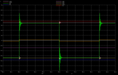
5) See the step response leading + trailing edge, a very limited transient, but it is > 200V/usec slew, so some important perturbation is expected. Ahh now I realise the weird response for step response, because point 1)
The input transistors dissipates ~ 130mW and the VAS ~ 410mW, BD's ~ 1.2W.
Cheers
Arturo
Thanks, Wahab,
It is obvious that you simmed a sightly different circuit, but
1) the input CSS's are somewhat 'floating' (without the servo) so the common node R29, R31 must be tied to GND (0V).
2) You did a different buffer + output but this should be of less importance, as you needed to adapt it to the output BJT's
3) This circuit also NEEDS the low pass filter C2 in my schem, and I've noticed that you used a order of magnitude lower impedance R30,R6, Mine is100R,1n cap and 75k in ||.
4) Ft is at 4 MHZ and the phase is about -1.45 radians ~ -83° wich gives > 90° of phase margin.
5) See the step response leading + trailing edge, a very limited transient, but it is > 200V/usec slew, so some important perturbation is expected. Ahh now I realise the weird response for step response, because point 1)
The input transistors dissipates ~ 130mW and the VAS ~ 410mW, BD's ~ 1.2W.
Cheers
Arturo
Attachments
I had a hard time understanding artu's amp at first , but realized it was similar to Dave tilbrook's AES6000. I degenerated it more conservatively , actually "grafting it" onto my leach prototype simulation. I was impressed by the clipping , transient ,and general robust behavior of the circuit. (Below 1) is the Bode for 60,40, and 20R degeneration - green trace. 47R was what I settled for , giving me 900k UG and 78db margin. This gave me about half of what Artu achieved, 125/Vus PERFECT symmetric slew along with stellar ... almost "soft clipping" behavior. I also have almost achieved PPM levels , but that is not my greatest concern. The FFT's are nice , too (2nd dominant - high order very low) .. this amp should sound VERY good. My "take" on it is (below 2 - CLX). I most likely will just drive a pair of laterals or my EF2 with it.
OS
Hi OS,
These are nice results. Unless I'm missing something you are just using straight TPC with it, as shown in the diagram you attached. In other words, it looks like you are using Artu's topology, but not really his compensation. Is that correct? There's not really any doubt that the circuit topology is good, just how the compensation worked and what it brought to the table. Sorry if I'm missing something here.
Looks like you degenerated by about 10 times as much, which certainly makes sense.
Cheers,
Bob
Hi Edmond, yes I've followed that thread and megajocke calculus and the results 'apples to apples' you posted, it is very interesting to verify how close each other both methods perform. For my amp TPC does better (despite it adds about 5ns group delay), but only verified by sims, not yet studied in deep, because my amp has another non-trivial compensation scheme that interacts with the TPC network, so it is a bit more complex, anyway the way I did, it reduces 10% ppm at low frec. and 20% ppm over 100KHZ + compared with the traditional Miller cap. Harmonics profile and phase margin stayed the same.
Cheers
Arturo
Cheers
Arturo
Hi Bob,
With the 3.3 OHM degeneration and the C5, C6 'dumpers', the phase margin is about 96° (f=4 MHZ). My goal was to stress as much as possible before reaching instability. If you strip C5,C6 caps the amp becomes unstable, no doubt, so in that case the need of a conventional degeneration is mandatory, and maybe also including the VAS degeneration as OS did in CLX. So why such little degeneration? because in part reduces distortion, but mainly it enhances the harmonic content distribution (empirically found), at a very high audio BW (exceeding 100KHZ), OS confirmed same results. The clipping is not as clean as OS CLX, but stable up to MHZ's. Anyway at first live tests I will start at much higher degeneration, and verify how much I can decrease it, and when reaching the final values I will test it with a 4GB HP spectrum analyser (with a friend that works at a telecom company), to see how much 'good' this thing is. The .68R are for stabilize the OPT darlingtons (4 totems which are very hard drived by the 0.8 OHM output impedance buffer) as much as possible to prevent thermal runaway (despite the thermal coupling), each one will be loaded with a current bias of 675 ma, so the total quiescent current wil be ~ 2.7 Amps. (Class A, at 100KZ a little bit AB). Yes you are correct the feedback network is TPC (a typo inherited from the previous schematic). As I said, I will have lots of room for experimentation, to tune the final values, and achieve as OS said a very good precise sound (I hope !!!)
Thank you very much for your attention Bob,
Cheers.
Arturo
Hi Arturo,
You are most welcome. With so much quiescent output stage current, you should have a large class A region and low distortion from the output stage for the most-frequent signal levels. It may also be the case that at high transient signal levels, where the output stage enters gm doubling, the added distortion from gm doubling may be quite well masked by the program material.
How hot do you expect your junction temperatures to be in thw quiescent state?
Cheers,
Bob
Hi Bob
~ 27 Watts per device (4 in || each leg), according to power derating figure for the BDX33C, the maximum temperature allowed is 100°C, so I will need massive heatsinking to reach 65° 0.162W/°C or better. Anyway I can reduce the Class A region to put a reasonable heatsink size without too much sacrificing it's characteristics. During vacations I will assemble it, so I'll see ...
Cheers
Arturo
How hot do you expect your junction temperatures to be in thw quiescent state?
~ 27 Watts per device (4 in || each leg), according to power derating figure for the BDX33C, the maximum temperature allowed is 100°C, so I will need massive heatsinking to reach 65° 0.162W/°C or better. Anyway I can reduce the Class A region to put a reasonable heatsink size without too much sacrificing it's characteristics. During vacations I will assemble it, so I'll see ...
Cheers
Arturo
should be 0.162C/W or 0.162Cdegrees/WErrata, 0.162W/°C should be 0.162°C/Watt
Cheers
Arturo
Thanks, Wahab,
It is obvious that you simmed a sightly different circuit, but
1) the input CSS's are somewhat 'floating' (without the servo) so the common node R29, R31 must be tied to GND (0V).
2) You did a different buffer + output but this should be of less importance, as you needed to adapt it to the output BJT's
3) This circuit also NEEDS the low pass filter C2 in my schem, and I've noticed that you used a order of magnitude lower impedance R30,R6, Mine is100R,1n cap and 75k in ||.
4) Ft is at 4 MHZ and the phase is about -1.45 radians ~ -83° wich gives > 90° of phase margin.
5) See the step response leading + trailing edge, a very limited transient, but it is > 200V/usec slew, so some important perturbation is expected. Ahh now I realise the weird response for step response, because point 1)
The input transistors dissipates ~ 130mW and the VAS ~ 410mW, BD's ~ 1.2W.
Cheers
Arturo
Hi Artu,
Not sure why one needs the input LPF created by C2 in order to evaluate stability and step response; indeed it is usually not done with an input LPF because it can disguise the real behavior of the amplifier. The ringing on the step still seems to indicate that the amp is not sufficiently stable.
BTW, forgive me if I asked you this before, but what tail current are you running in each of the LTPs?
Cheers,
Bob
Stability issue
Hi Bob,
At certain 'nasty' loads, specially with a 100nF cap. in parallel with the load (simmed with a speaker model and most parasitics I've extracted from the real PCB layout) the amp is 'unstable', but not enough to turn it into a full amplitude oscillator, so to be fair this amp. is not unconditional (over dumped) stable a ANY complex load, but for most of usual real loads (I hope). So here comes up a trade off between theory and real amp in practice (the tuning). I wish to preserve as much as possible the nice low distortion and FFT profile it shows. Also I changed the quiescent output current to 1.5A (375 ma per output totem) to restrict Class A to 30W output.
I've seen 'horrid' simulations and predictions that doesn't hold in reality (nothing happens) and some apparently nice 'stable numbers' that turns into spontaneous oscillators when turned on (this is more common).
The input LPT current is 14ma (very high) 7.2ma each diff. leg.
Cheers
Arturo
Hi Bob,
Not sure why one needs the input LPF created by C2 in order to evaluate stability and step response; indeed it is usually not done with an input LPF because it can disguise the real behavior of the amplifier. The ringing on the step still seems to indicate that the amp is not sufficiently stable.
At certain 'nasty' loads, specially with a 100nF cap. in parallel with the load (simmed with a speaker model and most parasitics I've extracted from the real PCB layout) the amp is 'unstable', but not enough to turn it into a full amplitude oscillator, so to be fair this amp. is not unconditional (over dumped) stable a ANY complex load, but for most of usual real loads (I hope). So here comes up a trade off between theory and real amp in practice (the tuning). I wish to preserve as much as possible the nice low distortion and FFT profile it shows. Also I changed the quiescent output current to 1.5A (375 ma per output totem) to restrict Class A to 30W output.
I've seen 'horrid' simulations and predictions that doesn't hold in reality (nothing happens) and some apparently nice 'stable numbers' that turns into spontaneous oscillators when turned on (this is more common).
The input LPT current is 14ma (very high) 7.2ma each diff. leg.
Cheers
Arturo
Attachments

Hi Bob,
At certain 'nasty' loads, specially with a 100nF cap. in parallel with the load (simmed with a speaker model and most parasitics I've extracted from the real PCB layout) the amp is 'unstable', but not enough to turn it into a full amplitude oscillator, so to be fair this amp. is not unconditional (over dumped) stable a ANY complex load, but for most of usual real loads (I hope). So here comes up a trade off between theory and real amp in practice (the tuning). I wish to preserve as much as possible the nice low distortion and FFT profile it shows. Also I changed the quiescent output current to 1.5A (375 ma per output totem) to restrict Class A to 30W output.
I've seen 'horrid' simulations and predictions that doesn't hold in reality (nothing happens) and some apparently nice 'stable numbers' that turns into spontaneous oscillators when turned on (this is more common).
The input LPT current is 14ma (very high) 7.2ma each diff. leg.
Cheers
Arturo
Hi Arturo,
I think we have some different philosophies. I believe that stability in amplifiers needs to be just about the top priority, under all forseeable reasonable use conditions. The pursuit of super-low distortion at the possible expense of other performance and behaviors is what is perhaps responsible for part of the bad rap that negative feedback has gotten.
I have said many times that amplifiers sound different because they misbehave differently. They often don't misbehave in detectable ways on the test bench, so that gives rise to the disconnect between measured results and listening results in real-world situations. This is partly responsible for those who want to throw measurements out the window, also not a good idea.
I have a suspicion that a number of amplifiers out there are occasionally bursting into parasitic oscillation under certain conditions of program material and real-world environment, giving rise to poor sound from an amplifier that otherwise one would think should sound very good.
Cheers,
Bob
First of all Bob, I also share with you that stability is of most important concern. My point is the extent of what is a reasonable condition is (that's where criterion and wisdom comes up), nothing is granted in a wide BW amp., there are many issues that simulations don't reveal, even I managed to include as parasitics as much I could of the layout done and used some models of real speakers. I am with you that NFB loop has been abused, that is not what I intend to do. The whole point with this design is to prove that C5,C6 improves stability as limits (and collapses arising) oscillation conditions that without these caps. turns would turn in burst or a permanent oscillating condition and at different values of degeneration, TPC or TMC compensations, bias points ... values and still preserve a nice FFT 'musical' profile a merit of VAS topology with or without my compensation scheme. The 3.3R is an extreme exercise, but I am very sure that with the help of this compensation scheme it will be possible a real degeneration setting below the 'traditional values', how much? really I don't know yet. When tested in reality by instruments and hearing the sound, I will be able to do a more concrete assessment, sure I will post the results.Hi Arturo,
I think we have some different philosophies. I believe that stability in amplifiers needs to be just about the top priority, under all forseeable reasonable use conditions. The pursuit of super-low distortion at the possible expense of other performance and behaviors is what is perhaps responsible for part of the bad rap that negative feedback has gotten.
I have said many times that amplifiers sound different because they misbehave differently. They often don't misbehave in detectable ways on the test bench, so that gives rise to the disconnect between measured results and listening results in real-world situations. This is partly responsible for those who want to throw measurements out the window, also not a good idea.
I have a suspicion that a number of amplifiers out there are occasionally bursting into parasitic oscillation under certain conditions of program material and real-world environment, giving rise to poor sound from an amplifier that otherwise one would think should sound very good.
Cheers,
Bob
Cheers
Arturo
I have exprience of an amplifier, whereas not stable on any load was ok if input signal rise/fall time was increased using a low pass filter. By having a look to output, all was ok on many loads. One day, I did some clipping tests at various frequencies for different loads and I found the point were all that transformed to a high power oscillator. Some BJT finished to the basket.
Since then, I go the way Bob goes by having unconditionnal stables amplifier with reasonable margins without limiting input signal bandwidth. After it's ok. Reducing bandwidth is an additionnal security.
This way I am far less nervous when connecting my DIY amp on an unknown speaker for a Rave Party.
I have exprience of an amplifier, whereas not stable on any load was ok if input signal rise/fall time was increased using a low pass filter. By having a look to output, all was ok on many loads. One day, I did some clipping tests at various frequencies for different loads and I found the point were all that transformed to a high power oscillator. Some BJT finished to the basket.
Since then, I go the way Bob goes by having unconditionnal stables amplifier with reasonable margins without limiting input signal bandwidth. After it's ok. Reducing bandwidth is an additionnal security.
This way I am far less nervous when connecting my DIY amp on an unknown speaker for a Rave Party.
Hi Macleod,
You bring up a good point. The stability of power amplifiers can be rather different in different operating regions. At minimum, we can define small-signal, large-signal and clipping regions. I can't tell you how many times I've seen amplifiers break out into a burst of oscillation on the falling slope at high amplitude of a sinewave just under clipping. The operating parameters of output transistors, in particular, go through a significan range of variation as their operating current varies from perhaps 100mA to almost 10A in some cases, and as their operating voltage varies from perhaps 50V to as little as 2V.
Cheers,
Bob
Bob:
Thank you for writing this book.
It is the Best book I have ever read on ANY electronic/technical subject.
IF there was anything else I would like to see as far as it is concerned, it would be a student work book to enhance its ability to be used as a text book.
It is truly perfect, and an outstanding master piece of work. NONE better.
I have a suspicion ...
Hi Bob,
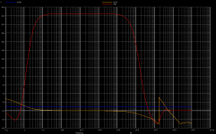
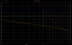
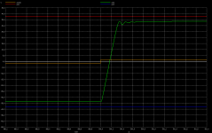
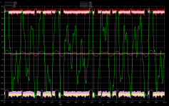
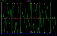
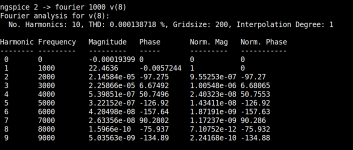
To put it more 'real' your assertions, I have done 2 simms. that shows the case. Both amps are the same (my design topology), without the LP input filter, signal DC coupled, the only difference is that one the 'unstable' runs without my compensation scheme (the values of the amp are slightly different from the original with a degeneration of 6.8R {enough low to show the truth of your assertion}). I've put a 'resonating load' at about 3MHZ to trigger the unstable condition (overshot while clipping is the resonance of the load itself). I've feed both amps with the same 'music material' at a rather high frequency (100KHZ), but it doesn't has importance (can be scaled to any freq.). So the input is asynchronous and has different levels of amplitude from low, medium, high, soft and hard clipping levels. Your suspicions are quite REAL as both amps are APPARENTLY reproducing the same 'music' while the unstable amp is oscillating at 20MHZ and music is modulating the oscillation showed in the first pix (RED,PINK,PALE YELLOW,PALE VIOLET traces at VAS input). Now with my compensation scheme (C5=C6=680pf) the stable reproduction in the second pix with the same 'resonating' load. I could say that this compensation scheme works pretty good as it not degrade slew nor distortion to any extent, I am very amused with this results. The third pix show FFT at 1KHZ 31 Watts RMS output of the compensated version.
Cheers
Arturo
Hi Bob,
I have said many times that amplifiers sound different because they misbehave differently. They often don't misbehave in detectable ways on the test bench, so that gives rise to the disconnect between measured results and listening results in real-world situations. This is partly responsible for those who want to throw measurements out the window, also not a good idea.
I have a suspicion that a number of amplifiers out there are occasionally bursting into parasitic oscillation under certain conditions of program material and real-world environment, giving rise to poor sound from an amplifier that otherwise one would think should sound very good.
To put it more 'real' your assertions, I have done 2 simms. that shows the case. Both amps are the same (my design topology), without the LP input filter, signal DC coupled, the only difference is that one the 'unstable' runs without my compensation scheme (the values of the amp are slightly different from the original with a degeneration of 6.8R {enough low to show the truth of your assertion}). I've put a 'resonating load' at about 3MHZ to trigger the unstable condition (overshot while clipping is the resonance of the load itself). I've feed both amps with the same 'music material' at a rather high frequency (100KHZ), but it doesn't has importance (can be scaled to any freq.). So the input is asynchronous and has different levels of amplitude from low, medium, high, soft and hard clipping levels. Your suspicions are quite REAL as both amps are APPARENTLY reproducing the same 'music' while the unstable amp is oscillating at 20MHZ and music is modulating the oscillation showed in the first pix (RED,PINK,PALE YELLOW,PALE VIOLET traces at VAS input). Now with my compensation scheme (C5=C6=680pf) the stable reproduction in the second pix with the same 'resonating' load. I could say that this compensation scheme works pretty good as it not degrade slew nor distortion to any extent, I am very amused with this results. The third pix show FFT at 1KHZ 31 Watts RMS output of the compensated version.
Cheers
Arturo
Attachments
Bob:
Thank you for writing this book.
It is the Best book I have ever read on ANY electronic/technical subject.
IF there was anything else I would like to see as far as it is concerned, it would be a student work book to enhance its ability to be used as a text book.
It is truly perfect, and an outstanding master piece of work. NONE better.
Keep that up and I might write another one
") .
.Seriously, thank you so much for those kind words and I really am thrilled that you like it so much.
I am indeed hoping to market it into the academic segment, and your idea is a good one. I think that audio would be a good "hook" to get young people more interested in electronics, especially analog electronics. I'm thinking that it might serve as a text in an audio engineering vocational school or in some community colleges. The late Marshall Leach wrote a very good book on audio and electroacoustics and used it as a text for a course he taught at Georgia Tech and it was quite successful.
Cheers,
Bob
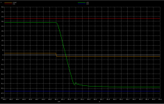
I coupled together the electrical model from Figure 18.1 of Bob's book, then used it, driven through the Edcor transformer. I just wanted to see what the tubes from the Millet Engineers Amplifier were looking at. First is just the load, second is the impedance which the tubes see:
Attachments
Hi,
I can understand that the LF load is reflected through the transformer to it's input. That explains the LF peaking and the lower Mid impedance of ~7k
But what is happening in the higher audio band? Why does the reflected impedance seem to hold fairly steady @ 7k and then at 40kHz it peaks?
I can understand that the LF load is reflected through the transformer to it's input. That explains the LF peaking and the lower Mid impedance of ~7k
But what is happening in the higher audio band? Why does the reflected impedance seem to hold fairly steady @ 7k and then at 40kHz it peaks?
Hi,
I can understand that the LF load is reflected through the transformer to it's input. That explains the LF peaking and the lower Mid impedance of ~7k
But what is happening in the higher audio band? Why does the reflected impedance seem to hold fairly steady @ 7k and then at 40kHz it peaks?
I went back and soldered it up again:
Edcor 8K into Cordell Load:
An externally hosted image should be here but it was not working when we last tested it.
Edcor with Infinity Kappa6
An externally hosted image should be here but it was not working when we last tested it.
Fisher400 with Cordell Load:
An externally hosted image should be here but it was not working when we last tested it.
- Home
- Amplifiers
- Solid State
- Bob Cordell's Power amplifier book