In my case, where I have 4 channels and the preceding signal stage in the amp ground sensing (differential signalling) made for an easy decision. A HBR is about half of the ground sense already, so it makes total sense to add the other half and enjoy the benefits having the ground levels between the boards explicitly separated but as local references. Factors like crosstalk are improved too.What do you think is the optimal layout for an amp where the channels must share a trafo winding?
Of course for those who have the amp only in the one chassis or choose to avoid opamps, this might not be so easy.
In my situation, the output transistors are not on the circuit board, but are hand wired across the back panel. The circuit loop for the speaker would be from the power supply, through the transistors, then ultimately back to the junction of the main filter capacitors. There is really no place on the circuit board to connect a speaker return, so that is connected (separate wires for each channel) via the shortest path back to a ground bus near the main capacitors.
I did read some earlier information from you that it is sometimes beneficial to not use large power wires for the output stage as the resistance of a smaller wire provides some resistance for decoupling. Since my output stages are fused at 2 or 2.5 amps, #22 wire is sufficient. I have added 10 µF capacitors near the transistors for decoupling. Additionally, the main ± power for the circuit board is separate wires from the fuses, so does not share the power wire to the output transistors.
As for twisting the output transistor power wires, I don't get it. I understand cancellation, but the current pulses are not simultaneous so there can't be any cancellation. If the speaker return was included, then yes, as it would have current anytime there was heavy current in either power wire. In my case, this would require the speaker returns to be routed back to the output transistors, then twisted back to the main power supply via the back panel fuses. This would add a good foot of wire to the speaker returns. Which is better?
Hi Fred,
The technique of twisting the + and - rail wires together is not to cancel currents, but rather to sum the two class AB half-wave-rectified currents back into a sinewave (when the signal is a sinewave) so that its net field is more linear.
Cheers,
Bob
Plus, it is only harmonic distortion if there is IV phase shift.
I don't understand this statement here. What does harmonic distortion have to do with phase or phase shift?
Harmonic distortion arises from wave shape distortion of any kind.
Still trying to understand better what the problem is, not convinced the output voltage of 19,99V is correct, the 10mV is outside the feedback loop. It would mean that 10mV is over the 10R HBR. That is also not correct. Going around in circles here.
I'm lost, do you have a schematic?
Plus, it is only harmonic distortion if there is IV phase shift.
That reads incorrect as formulated. Phase shift is not directly related to distortion because of the very interesting mathematical properties of sine waves. The integral (inductor current) and derivative (capacitor current) of a sine wave, are also sine waves.
Poldaaudio,
Rather than the ‘crying out aloud’ bit, how about some scope shots or a diagram showing why your approach is better? Measurements?
I would thing that in a multi-channel system, terminating the speaker return back at each amp module would be even more important.
Try thinking about the star ground on the amp module as the reference. You then have two loops - both terminating at the star ground on the module star ground. As long as you provide sufficient wideband bulk decoupling on the module PCB and the supply wires from the PSU are twisted (minimize loop area and EM radiation) you are good to go.
Comments relate to postBob Cordell's Power amplifier book. You are correct about distortion of sine waves. What I meant to say is that without phase shift there is only a small amplitude error.I'm lost, do you have a schematic?
That reads incorrect as formulated. Phase shift is not directly related to distortion because of the very interesting mathematical properties of sine waves. The integral (inductor current) and derivative (capacitor current) of a sine wave, are also sine waves.
In my opinion, the 19.99V is incorrect as the 10mV is outside the feedback loop.
Last edited:
Yes, this is a surprisingly complex topic and it's hard to find a layout without faults. And I agree the optimal layout can change between implementations. I think Bonsai has come closest to making a complete writeup on the topic, but somehow whenever I read it I'm left unsatisfied. Jneutron has shared some advanced ideas from his work on scientific equipment in other threads.
What do you think is the optimal layout for an amp where the channels must share a trafo winding?
Ok - I accept that you are left unsatisfied after reading the presentation. But unless you are much more specific, I cannot address your concerns.
What is it that you do not like about the presentation, or that you feel is lacking?
Here it is, page 58:
http://hifisonix.com/wordpress/wp-content/uploads/2019/02/Ground-Loops.pdf
What I don't like is the reliance on ground breaking resistors which only add 15db or so of rejection. But that seems to be a necessary evil.
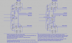
I made my own diagram. I wouldn't be surprised if this has been proposed on DIYaudio before, but it's easy to pass over this EMC stuff without seeing the significance. The 10nF capacitors entirely break the internal ground loop between channels and between PSU returns and input. This layout is no longer susceptible to magnetic interference when the RCA shields are shorted, as there is no need for any loop area before the 10R resistors. The resistors are no longer as critical as they were, but they still help with common mode hum from the source.
I'm not sure 10nF is enough, I think 330nF would be a fairly safe value.
http://hifisonix.com/wordpress/wp-content/uploads/2019/02/Ground-Loops.pdf
What I don't like is the reliance on ground breaking resistors which only add 15db or so of rejection. But that seems to be a necessary evil.
I made my own diagram. I wouldn't be surprised if this has been proposed on DIYaudio before, but it's easy to pass over this EMC stuff without seeing the significance. The 10nF capacitors entirely break the internal ground loop between channels and between PSU returns and input. This layout is no longer susceptible to magnetic interference when the RCA shields are shorted, as there is no need for any loop area before the 10R resistors. The resistors are no longer as critical as they were, but they still help with common mode hum from the source.
I'm not sure 10nF is enough, I think 330nF would be a fairly safe value.
Attachments
Last edited:
Comments relate to postBob Cordell's Power amplifier book. You are correct about distortion of sine waves. What I meant to say is that without phase shift there is only a small amplitude error.
In my opinion, the 19.99V is incorrect as the 10mV is outside the feedback loop.
The diagram is correct. The feedback reference is on the other side of the ground resistance, as it is blocked by the 10R resistor. If the feedback reference were at speaker return before the ground resistance, you would be correct. However this would likely result in a number of other layout problems.
I disagree, the 10mV is outside the feedback loop. You could increase the ground resistance so that the voltage drop is 1 V. Would that mean that the output would only be 19V?
The voltage across the speaker would be 19V. The voltage to ground at the amp output would be 20V.
How does the 10mV across the ground resistance change any of the feedback voltages? That 10mV is no different than if you put a resistor in series with the speaker and measured the voltage drop across it.
You didn't answer my question of how the 10mV affects the feedback loop. The 10ohm resistor is only shunting the ground resistance. They share the same nodes. One pin to speaker return, the other pin to ground. The resistors are in parallel. There is no voltage between the two ground symbols, they are the same node.
On the other hand if you disconnect the input return from ground, you will get 20V across the speaker because the signal reference is floating at the speaker return voltage.
On the other hand if you disconnect the input return from ground, you will get 20V across the speaker because the signal reference is floating at the speaker return voltage.
I think poldaaudio has a valid point and it should be taken into consideration.
Thank you!
- Home
- Amplifiers
- Solid State
- Bob Cordell's Power amplifier book