A significant choice that I make is to not route the loudspeaker neutral line back to the power supply star ground; I always return the speaker current to the amplifier board.
Well if you have individual amplifier modules all powered from a common power supply, unless the signal inputs and speaker return grounds are not tied to a single point in your hierarchical star-earthing scheme (ideally where the chassis is ground-terminated), then you will almost certainly* have bypass-capacitor ripple currents flowing through your signal ground paths/loops in one part/way or another.
* unless you have employed signal transformers to galvanically separate the signal input grounds.
Last edited:
Thanks Bob.
Yes, I definitely see additional issues with test equipment connected. Even tried an isloation transformer on the scope. I'm not using ground planes. My circuit boards are actually perf boards with component leads folded over and connected. This is more rugged than pc board foil and allows for major changes without producing a new board. In fact, the boards pictured below have now been rebuilt twice since the pictures were taken.
During the analysis, I looked at the layout of my Harman Kardon Citation 21 preamp and it appears to use the star-on-star grounding as you mention and is quiet. That's what I ended up doing with this design.
Now working on the power amp section. The receiver is a Fisher 600-T which used 4 transistors in series to handle the voltage. So the physical layout is ideal for parallel output transistors in a modern design. I am deviating from one of your preferences, using EF2 rather than EF3. The output transistors have beta of around 60 and the drivers are over 200. Power is ±38 V no load and I'm looking at about 50 watts into 8 Ω. Driver standing current is about 50 mA and VAS about 10 mA. Maybe not perfect, but certainly better than the 1962 RCA transistor manual, germanium PNP, original design.
Have spent MUCH time reading your first edition book (along with material from Self, Leach, Andrew Russell, and others) and looking forward to your new edition.
Images of top and bottom of one of the preamp boards .....
1827
An externally hosted image should be here but it was not working when we last tested it.
1828
An externally hosted image should be here but it was not working when we last tested it.
Fred
Hi Fred; nice prototyping. This approach is almost exactly how I implement a first prototype on perf board. Doing it this way, taking advantage of direct component wire connections on the wiring side of the board, can subsequently give you a head start to a PCB layout.
Cheers,
Bob
Well if you have individual amplifier modules all powered from a common power supply, unless the signal inputs and speaker return grounds are not tied to a single point in your hierarchical star-earthing scheme (ideally where the chassis is ground-terminated), then you will almost certainly* have bypass-capacitor ripple currents flowing through your signal ground paths/loops in one part/way or another.
* unless you have employed signal transformers to galvanically separate the signal input grounds.
Not necessarily, but you do touch on a couple of things that are important to keep in mind. First of all, it is indeed important to be mindful of how and where power supply bypass currents flow into ground. You also don't want to corrupt the ground with ripple current of half-wave-rectified signal current from the output stage. Although some ground points may be more corrupt than others, it is especially important that ground near the input stage not be corrupt.
The progressive bypassing that I use reduces the amount of garbage on the rails as they progress back toward the input circuits, and this means that bypasses to ground closer to the input circuitry will dump less garbage into the ground. Another very effective technique is to feed the input circuit's rails from a capacitance multiplier. This allows the input circuit's rails to be essentially referenced to the signal ground in that area.
I deliberately want the speaker currents to circulate locally on the amplifier board at high frequencies. This is aided by the fact that I place 1000 uF bypass capacitors right on the amplifier board where the rails come in from the power supply. In connecting the speaker neutral to the amplifier board, bear in mind that the speakers float and their neutrals for 2 channels are not connected together.
One other point that your comment touches on is the potential advantage of so-called dual-mono stereo amplifiers, where the use of separate power supplies for each channel reduces opportunities for ground loops and the like. Ground loops that may be formed by the neutrals of the left and right input interconnect cable are especially important to avoid.
Cheers,
Bob
Not necessarily, but you do touch on a couple of things that are important to keep in mind. First of all, it is indeed important to be mindful of how and where power supply bypass currents flow into ground. You also don't want to corrupt the ground with ripple current of half-wave-rectified signal current from the output stage. Although some ground points may be more corrupt than others, it is especially important that ground near the input stage not be corrupt.
The progressive bypassing that I use reduces the amount of garbage on the rails as they progress back toward the input circuits, and this means that bypasses to ground closer to the input circuitry will dump less garbage into the ground. Another very effective technique is to feed the input circuit's rails from a capacitance multiplier. This allows the input circuit's rails to be essentially referenced to the signal ground in that area.
I deliberately want the speaker currents to circulate locally on the amplifier board at high frequencies. This is aided by the fact that I place 1000 uF bypass capacitors right on the amplifier board where the rails come in from the power supply. In connecting the speaker neutral to the amplifier board, bear in mind that the speakers float and their neutrals for 2 channels are not connected together.
Yes, necessarily. Your comment that " the speakers float and their neutrals for 2 channels are not connected together" makes no sense.
All that needs to be said (really!) is that the ground returns for the signal input channels (unless galvanically isolated, by, say, transformers, as I mentioned) are one and the same and do NOT "float" with respect to each other.
I find it amazing that hardly anyone seems to be able to instantly conceptualize the problem here.
One other point that your comment touches on is the potential advantage of so-called dual-mono stereo amplifiers, where the use of separate power supplies for each channel reduces opportunities for ground loops and the like. Ground loops that may be formed by the neutrals of the left and right input interconnect cable are especially important to avoid.
Cheers,
Bob
Well of course it does, which is why I specifically made the distinction by opening with "Well if you have individual amplifier modules all powered from a common power supply"....................
Yes, necessarily. Your comment that " the speakers float and their neutrals for 2 channels are not connected together" makes no sense.
All that needs to be said (really!) is that the ground returns for the signal input channels (unless galvanically isolated, by, say, transformers, as I mentioned) are one and the same and do NOT "float" with respect to each other.
I find it amazing that hardly anyone seems to be able to instantly conceptualize the problem here.
Well of course it does, which is why I specifically made the distinction by opening with "Well if you have individual amplifier modules all powered from a common power supply"....................
Your assertion that my comment regarding the speakers floating makes no sense (at least to you) suggests that you have not thought through the issue sufficiently.
If the neutrals of the two speakers were connected together, say for illustrative purposes, at the loudspeaker ends (a silly thing to do), then a ground loop would result. That ground loop's effects would likely be exacerbated in the case where the speaker neutrals are returned to the amplifier boards. If the loudspeakers each float, such a loop cannot be created.
Think about it.
Connecting the speaker returns to the amplifier board, as opposed to a power supply ground, does indeed not necessarily create a grounding problem. Could a very inexperienced person cause it to create a grounding problem? Probably, but so could such a person have a grounding problem with a star ground. There will always be someone who can screw up any architecture.
There are many ways to properly skin a cat in the hands of a skilled designer who pays attention to detail. Grounding can be a bit of an art, and more than one way can be right.
Another example of grounding-related issues where different approaches are advocated is the connection from the amplifier board back to the power supply. In one approach, the positive and negative rail lines are twisted together and the ground is returned as a separate wire. In a second approach, all three wires, positive rail, negative rail and ground are twisted together and returned to the power supply. Either approach can be made to work well in the proper context. I happen to prefer twisting the three together. I believe Doug Self prefers the first approach. Both approaches yield excellent performance.
Here is another one for you to chew on, and probably argue about. What AWG wire should be used for the wires connecting the power supply to the amplifier board? Given that signal currents in the tens of amps may flow briefly at times, does the wire need to be really heavy, like 12 or 14 AWG? Or is a smaller AWG OK as long as it won't overheat and/or drop too much voltage? If the resistance in the path is, say 50 milli-ohms to 100 milli-ohms matter? If so, why? Does it depend on the details of the amplifier design? Probably.
What AWG do you think the bond wires are inside a power transistor? They are quite small, but that is partly due to the fact that the distance is small.
Cheers,
Bob
I also always return the speaker -ve to the amplifier module board. As long as the local bulk decoupling on the board is sufficient, and is wideband, you will keep all but LF currents off the 0V wire from the module back to the PSU.
If you do not do this, you are radiating HF currents (signal related of course) in your amp, and as Bob points out, the HF current loops will also be much larger.
The 0V reference for any amplifier for anything above a few tens of Hz is the star junction on your amplifier PCB. If you twist the supply wires from the PCU to the amp module tightly together, and you keep signal and power grounds separated but join them on the star on the amplifier module, you can create noise free amps.
Anyway, I don't want to gate crash Bob's thread, so I'll step out of this for now.
I also always return the speaker -ve to the amplifier module board. As long as the local bulk decoupling on the board is sufficient, and is wideband, you will keep all but LF currents off the 0V wire from the module back to the PSU.
If you do not do this, you are radiating HF currents (signal related of course) in your amp, and as Bob points out, the HF current loops will also be much larger.
The 0V reference for any amplifier for anything above a few tens of Hz is the star junction on your amplifier PCB. If you twist the supply wires from the PCU to the amp module tightly together, and you keep signal and power grounds separated but join them on the star on the amplifier module, you can create noise free amps.
Anyway, I don't want to gate crash Bob's thread, so I'll step out of this for now.
Thanks Bonsai. You are exactly right.
Cheers,
Bob
Your assertion that my comment regarding the speakers floating makes no sense (at least to you) suggests that you have not thought through the issue sufficiently.
If the neutrals of the two speakers were connected together, say for illustrative purposes, at the loudspeaker ends (a silly thing to do), then a ground loop would result. That ground loop's effects would likely be exacerbated in the case where the speaker neutrals are returned to the amplifier boards. If the loudspeakers each float, such a loop cannot be created.
Think about it.
Connecting the speaker returns to the amplifier board, as opposed to a power supply ground, does indeed not necessarily create a grounding problem. Could a very inexperienced person cause it to create a grounding problem? Probably, but so could such a person have a grounding problem with a star ground. There will always be someone who can screw up any architecture.
There are many ways to properly skin a cat in the hands of a skilled designer who pays attention to detail. Grounding can be a bit of an art, and more than one way can be right.
Another example of grounding-related issues where different approaches are advocated is the connection from the amplifier board back to the power supply. In one approach, the positive and negative rail lines are twisted together and the ground is returned as a separate wire. In a second approach, all three wires, positive rail, negative rail and ground are twisted together and returned to the power supply. Either approach can be made to work well in the proper context. I happen to prefer twisting the three together. I believe Doug Self prefers the first approach. Both approaches yield excellent performance.
Here is another one for you to chew on, and probably argue about. What AWG wire should be used for the wires connecting the power supply to the amplifier board? Given that signal currents in the tens of amps may flow briefly at times, does the wire need to be really heavy, like 12 or 14 AWG? Or is a smaller AWG OK as long as it won't overheat and/or drop too much voltage? If the resistance in the path is, say 50 milli-ohms to 100 milli-ohms matter? If so, why? Does it depend on the details of the amplifier design? Probably.
What AWG do you think the bond wires are inside a power transistor? They are quite small, but that is partly due to the fact that the distance is small.
Cheers,
Bob
Transistor bond wires? What? You are obfuscating.
DIYAUDIO - the place where even the most straightforward technical truths will be denounced and met with violent opposition every single, minute, step of the way.
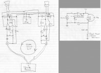
I have attached a simplified scribbled drawing that illustrates the problem that everyone seems to be missing. It shows a pair of typical amplifier modules with the speaker returns terminated at the amplifier PCB and the amplifier modules sharing a common power supply.
Between points A and B, due to the finite impedance of the ground return wires to the PSU, a potential difference will be induced by both the speaker signal return current in addition all of the rubbish coupled from the power supply rails into the ground return by the local supply rail bypass capacitors.
So we now have separate "signal ground" areas on each power amplifier board. The problem occurs when the signal source is plugged in, forming a loop by shoring these signal ground together.
The unavoidable potential difference developed between points A and B is now impressed across the signal ground. A common "cure" to this problem is to attempt to isolate the "clean" signal grounds on each amplifier PCB by connecting it to the "dirty" power ground via a low value (typically 10 ohms or so) resistor.
This approach reduces, but does not eliminate the issue because any potential difference developed across these resistors is still a signal ground disturbance and essentially subtracts from the voltage developed across the speaker. The disturbing thing here is that the effects of this signal ground loop will not show up in distortion measurements unless the signal grounds at the input jacks are deliberately shorted together (as they are when a signal source is connected). I have seen amplifier distortion performance and inter-channel cross-talk degraded by anything up to 30dB by this simple expedient.
Separately returning the speaker ground returns to the individual amplifier boards is perfectly fine when each amplifier has its own independent power supply, but no matter how much anyone many care to moan, it is a sub-optimal and inferior approach when all of the amplifier modules share a common power supply.
Attachments
Last edited:
Hi Fred; nice prototyping. This approach is almost exactly how I implement a first prototype on perf board. Doing it this way, taking advantage of direct component wire connections on the wiring side of the board, can subsequently give you a head start to a PCB layout.
Cheers,
Bob
Thank you. While these look like prototypes, they are actually final as I don't make "real" printed circuit boards. Notice that the edges are filed clean so they don't look like postage stamps and the connections use actual terminals rather than random wires sticking out. These have also been revised a few times, even since these photos.
.....
I deliberately want the speaker currents to circulate locally on the amplifier board at high frequencies. This is aided by the fact that I place 1000 uF bypass capacitors right on the amplifier board where the rails come in from the power supply. In connecting the speaker neutral to the amplifier board, bear in mind that the speakers float and their neutrals for 2 channels are not connected together.
.....
Cheers,
Bob
In my situation, the output transistors are not on the circuit board, but are hand wired across the back panel. The circuit loop for the speaker would be from the power supply, through the transistors, then ultimately back to the junction of the main filter capacitors. There is really no place on the circuit board to connect a speaker return, so that is connected (separate wires for each channel) via the shortest path back to a ground bus near the main capacitors.
I did read some earlier information from you that it is sometimes beneficial to not use large power wires for the output stage as the resistance of a smaller wire provides some resistance for decoupling. Since my output stages are fused at 2 or 2.5 amps, #22 wire is sufficient. I have added 10 µF capacitors near the transistors for decoupling. Additionally, the main ± power for the circuit board is separate wires from the fuses, so does not share the power wire to the output transistors.
As for twisting the output transistor power wires, I don't get it. I understand cancellation, but the current pulses are not simultaneous so there can't be any cancellation. If the speaker return was included, then yes, as it would have current anytime there was heavy current in either power wire. In my case, this would require the speaker returns to be routed back to the output transistors, then twisted back to the main power supply via the back panel fuses. This would add a good foot of wire to the speaker returns. Which is better?
Fred you didn't say whether the LM4562 you're using are the National Semi part the or TI part.
If they are the National semi part it would be interesting to to see if the TI part exhibits the same issue.
The op amps, per the DigiKey web site, are TI, even though they have LM part numbers and a National logo. Maybe old National stock?
My assumption as to what was happening is that there is some inductance in the separate wires (signal ground and bypass ground) along with some inductive or capacitive coupling in the amplifier between the 2, creating a resonant loop. My testing for this is limited to a 10 MHz scope and frequencies were as high as 7 MHz at approximately 5 mV peak, pushing the limits of the scope. Apparently the small resistor between the wires eliminates the resonance. The final design uses only one ground lead for both, separated at the amplifier board by 4.7 Ω.
I was also dealing with another multi MHz oscillation in the power amplifier that was only present when the output transistors were connected. Figuring that the problem was in the actual output stage, I spent a lot of time chasing the wrong part of the circuit. That problem was finally cured with a 220 pF capacitor between the VAS input and the - supply. We'll see if that works after the final installation. There was also an added series 560 Ω / 47 pF in parallel with the feedback resistor (per the Marshall Leach design) that seemed to be aggravating the situation and was also eliminated. I had reservations about the 220 pF, but square wave response looks very good even well beyond 20 kHz.
I have attached a simplified scribbled drawing that illustrates the problem that everyone seems
to be missing. It shows a pair of typical amplifier modules with the speaker returns terminated
at the amplifier PCB and the amplifier modules sharing a common power supply.
I believe that many here already do understand this problem.
.
Separately returning the speaker ground returns to the individual amplifier boards is perfectly fine when each amplifier has its own independent power supply, but no matter how much anyone many care to moan, it is a sub-optimal and inferior approach when all of the amplifier modules share a common power supply.
Bob is correct here, the speaker (load ground) should be joined to the signal ground and then returned to the local PCB star ground. Connecting the speaker ground and signal grounds to separate places means a error voltage develops between the two. This error voltage is worse if you connect the speaker ground to the offboard main power supplies ground which carries heavy current pulses.
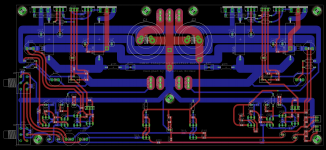
Please have a look at professional, low distortion PCB designs, they always return the load ground to the signal ground on the PCB, and then the local star ground is returned to the main power supply star ground. Have a look at the attached low distortion (0.004% THD) design and see that the signal ground on the left meets the speaker ground on the right and then is joined to the local PCB star ground in the centre. There is no hum breaking resistor. This leads to dead silent amplifier modules, no hum.

Last edited:
For crying out loud!
That speaker return and signal ground termination is perfectly, 100% fine so long as the amplifier module has its own independent power supply, and it doesn't in any way contradict a single thing that I have written!
If, on the other hand, a common power supply is used amongst multiple amplifier modules, then it is sub-optimal (hum-breaking resistors or not!) for exactly the reasons I detailed with a schematic diagram in my previous post.
In this case an "ideal" wiring arrangement, as far as signal ground integrity goes, can only be approached if BOTH the speaker ground returns and the signal input grounds all share a common earthing point (although the speaker grounds can be actually be a terminated a little bit down stream in the star-earthing hierarchy).
Both Cordell's and Self's books are lacking and limited in this department, but the arrangement that Self shows where the speaker and signal grounds all share a common return is in fact the superior method when all amplifier modules share a common power supply. When the amplifier modules have their own, independent power supplies, then the opposite is true.
Neither author, as far as I am aware, even delves as deep as suggesting the most optimal earthing arrangement might as a matter of fact actually be different depending on how the amplifier modules are powered (independent power supplies or not).
Last edited:
Yes, this is a surprisingly complex topic and it's hard to find a layout without faults. And I agree the optimal layout can change between implementations. I think Bonsai has come closest to making a complete writeup on the topic, but somehow whenever I read it I'm left unsatisfied. Jneutron has shared some advanced ideas from his work on scientific equipment in other threads.
What do you think is the optimal layout for an amp where the channels must share a trafo winding?
What do you think is the optimal layout for an amp where the channels must share a trafo winding?
Agree with that, the ground layout is so important to get the best out of a design and very little to be found in the books or online.
Still trying to understand better what the problem is, not convinced the output voltage of 19,99V is correct, the 10mV is outside the feedback loop. It would mean that 10mV is over the 10R HBR. That is also not correct. Going around in circles here. Plus, it is only harmonic distortion if there is IV phase shift.
Still trying to understand better what the problem is, not convinced the output voltage of 19,99V is correct, the 10mV is outside the feedback loop. It would mean that 10mV is over the 10R HBR. That is also not correct. Going around in circles here. Plus, it is only harmonic distortion if there is IV phase shift.
- Home
- Amplifiers
- Solid State
- Bob Cordell's Power amplifier book