I believe you are confusing the DC voltage (indeed approximately constant) with the AC Vbe voltage. Drawing the equivalent schematic using the bipolar small signal model will show the difference.
As usual, large signal vs. small signal models can be confusing...
No I get that, it's only the varying Vbe that would appear, but with the very small current excursions we're talking a couple of mV across the Cm. In parallel to the dynamic b-e impedance.
Jan
No I get that, it's only the varying Vbe that would appear, but with the very small current excursions we're talking a couple of mV across the Cm. In parallel to the dynamic b-e impedance.
So the voltage is no longer "absolutely constant", we are talking magnitudes now
 .
.Really, I don't understand what's bothering you here. The rule of (manually) calculating pole-zeroes is to get each cap (Cb'e, Cb'c), apply a current/voltage source (whatever is more convenient) at it's terminals (while all other caps are disconnected) and determine the impedance (it will always have a real part only, since no other reactive components exist). This impedance multiplied by the cap value will be 2*PI*fpole (or zero). In this case, at the node of interest, you have at least 2*Cb'e of the transistors in the current mirror, plus whatever comes from the signal transistors Cb'c. As the conductance at the Cb'e terminals is certainly not zero (it's at least 2/Rb'e of the mirror transistors), here's your "mirror pole".
IMO, this kind of confusion is what simulators are doing to humans. The fact that one doesn't have access to the internal nodes of the device model.
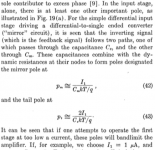
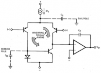
Minimalists prefer not to put the signal through another two (!) highly nonlinear devices. They also prefer to avoid what James Solomon's educational article calls "the mirror pole" as shown in his Figure 19(a), attached below.
A link to the Solomon article appears in post #7322 of this thread, among many other places.
_
Hi Mark, I just finished reading the paper you suggested, it is a great one! thank you for the suggestion, however the paper is taylored primarily towards IC designed opamps, with very low LTP currents in the order of 1-10 uAmps.
Minimalists prefer not to put the signal through another two (!) highly nonlinear devices.
How is a current source non linear? Twice the load, twice the voltage.
And why dont minimalists just use one transistor?
I see, so using a current mirror not only doubles the transconductance but also the Slew Rate!, whilst helping reduce distortion by keeping the collector currents balanced, it seems like that current mirror is a huge bargain.
It is a bargain, but yes and no on the doubling of slew rate. While the current mirror doubles the amount of current that the IPS can deliver to the VAS, doubling the slew rate for a given value of Miller compensating capacitor, it also doubles the transconductance. This means that, for the same gain crossover frequency and feedback stability, we must double CM, bringing the slew rate back down to where it was, all else remaining the same.
Cheers,
Bob
Minimalists prefer not to put the signal through another two (!) highly nonlinear devices. They also prefer to avoid what James Solomon's educational article calls "the mirror pole" as shown in his Figure 19(a), attached below.
A link to the Solomon article appears in post #7322 of this thread, among many other places.
_
The current mirror is not really a highly nonlinear device, especially if it is degenerated, as it always should be.
The mirror pole is at a quite high frequency in any reasonably designed discrete power amplifier. Consider an IPS with 2mA tail current and 1 mA in each transistor. Its current mirror load will also have 1 mA in each of its transistors. the re' of the current mirror transistors will be about 26 ohms. If we degenerate the current mirror by about 10:1 with 220-ohm emitter resistors, the impedance at the node in question (the anode of the diode-connected transistor) will be on the order of 250 ohms. If the stray capacitance at that node is 5 pF, then the pole will be at about 128 Mhz, way above the frequency range we need to consider. Because of the way that the current mirror gain path works, a pole-zero pair will actually be created, with the zero about an octave above the pole. There is thus essentially no problem or degradation for an audio power amplifiers.
Cheers,
Bob
minimalists (e.g. the famous designer in post #9136) use just one resistor.
_
I recognize that from his first published design which appeared in Audio magazine (RIP). I've got the specified power transformer for that PA... I recall Bob had a rather ambitious construction project published in the same magazine. I've got PCBs, ICs and switches for that...
Jeff
A question for Bob (or others) while we wait for the new edition.
I have started to look at quasi-saturation in transistors, in particular the reduction of Ft.
There is parameter QCO that affects this.
But in the 1st edition of your book you discuss VTF that seems to have a similar effect.
Any idea how the two parameters are related?
Best wishes
David
OK, I think I have the answer, both control Ft droop at low Vce but VTF isn't effective at low currents, where QCO presumably dominates.
Any further information still appreciated.
Last edited:
They're not related, the quasi-saturation was added to the model long after Vtf.
In this PDF it specifies NOT to use Vtf to fit the quasi-saturation region.
http://www.idea2ic.com/PlayWithSpice/pdf/G U M M E L - P O O N.pdf
In this PDF it specifies NOT to use Vtf to fit the quasi-saturation region.
http://www.idea2ic.com/PlayWithSpice/pdf/G U M M E L - P O O N.pdf
They're not related, the quasi-saturation was added to the model...
They are not equivalent but I would say they are related, they both affect the behaviour of Ft at low Vce.
However, not worth a quibble about the words.
In this PDF it specifies NOT to use Vtf to fit the quasi-saturation region.
Thanks for the reference.
They don't model q-s at all, so I read it as "keep out of q-s to determine VTF correctly".
Kind of supports my idea, the two aspects overlap to some extent.
My initial expectation is that QCO should be done first, because it will affect Ft fall off at all currents, then do VTF for any additional fall off at hi currents.
That's the reverse of the historical order they appeared, I could try to experiment with this to see if it works.
You (or anyone else) have any measurement data for Ft at low Vce?
Best wishes
David
The Hfe-vs-Ic chart is usually made at low voltage where the Hfe droop is largely defined by quasi-saturation. That is why it is a bad idea to fit only the Hfe vs Ic chart. At that voltage it may be correct, but at every other operating point it will be very wrong. If instead you fit the Ic vs Vce chart, your Hfe vs Ic result may not be perfect but the model will be much better as a whole.
The Ft vs Ic chart can be considered similarly. You can compare the Ft and Ic charts and see whether part of the Ft measurement is in the quasi-saturation region. Then you can use the Tf parameters for the curve before that point and use Qco for the portion that is in quasi-saturation.
But of course you want to have a datasheet with both an Ft chart and a Ic vs Vce chart.
....model test AKO:NPN npn...
Seems likely someone would have noticed if it had no effect at all.
On the other hand I have seen quite a few models with QCO=0.02, which implies a capacitance in the order of 20,000 uF.
This also seems rather unlikely
and surely would make a difference to the performance if QCO works, and yet no one seems to have noticed.Can you post the ASC of your test?
Best wishes
David
I seem to remember encountering this before, I couldn't get Qco to do anything in AC analysis, therefore no way to fit Qco, therefore no Qco included in the model. I've reported bugs like this to LTspice before. Notice that the Q-S parameters Cn and D also appear to do nothing. Sometimes it's just mismanaged flags in the model subcircuit.
I have been thinking about the placement of Qco in the model subcircuit. Qco is modeled as a capacitor connected to the base, with the other connection between the collector and Rco. Rco is zero at high voltages but rises in quasi-saturation as Vce nears zero.
For a power amp power output BJT, Rco will probably be under 1 ohm. Since the collector impedance seen in an amplifier is defined by the zobel at 3.3R, 6.8R, 10R or whatever, the addition of Rco even at it's highest does not cause a substantial increase in collector load resistance and therefore Miller effect induced BW loss.
So I think this may be Moby Dick's whale where power amps are concerned.
A situation where it may realistically have a large impact is a TO92 common emitter amp driving a very low resistance, say 50 ohms. But for this to happen it has to be in quasi-saturation and Rco has to be significant compared to 50 ohms.
I'm looking at figure 3 here:
http://www.joerg-berkner.de/Fachartikel/pdf/1997_ICCAP_UM_Berkner_QS_Model_Parameterextraction.pdf
Which gives the equation for the capacitance in the subcircuit as:
Qo = QCO*[K(Vbc)−1−GAMMA / 2]
Where
K(v) = sqrt(1+gamma*exp(v/vt))
Last edited:
For a power amp power output BJT...
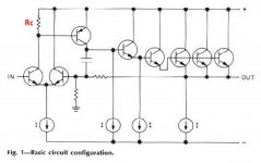
I am interested in the Baxandall (AKA Boxall) Super pair in the VAS rather than OPS.
So still relevant to me.
Best wishes
David
- Home
- Amplifiers
- Solid State
- Bob Cordell's Power amplifier book