In my system, I can hear a difference simply by changing the phase of any AC power cord.
(Easy to measure the best one looking at Voltages between the two grounds before connecting them together.)
I have a little headphone amplifier that I used professionally witch can be powered both by AC or by batteries. The difference is amazing.
I have never had that issue in decades .... I would say the Xfmr type and/or grounding of transformer and its mounting (isolated from chassis etc) isn't as good as it should be. Also, some RFI filter cap on ac line to ground adds leakage. However, if I didn't want to do anything about the source/cause of the leakage, I would use an isolation transformer on the offending gear. Not a Bal ips.
THx-RNMarsh
Last edited:
We are in accord here. I didn't want to refer to the imperfect real-world implementation of the mirror and summing point. Rather, I was wondering whether exactly all distortions would cancel in a thought experiment. Since the transistors of the input diff pair are always driven into different directions of the exponential curve with different transconductance slopes, I really would be surprised.
The main point, related to some simulation results presented on the previous pages, was: two nonlinear elements, surrounded by a finite-gain ideal loop, probably won't lead to exact linear behaviour.
BTW, do you see a reason to worry about stability of a 3T mirror "with EF helper"? Simulating it, one can easily get phase margins of only 30 degrees, and some people even talk of peaking in such a mirror.
The fitting of 2T VAS and 3T mirror is indeed nice. With a 2T mirror, one has to increase emitter resistors. But balancing also becomes more critical, since headrooms are smaller.
Cheers,
Matthias
Yes, stability of a 3T mirror has to be watched. Usually, any pair of transistors in a tight loop at HF should be watched carefully for stability issues. This includes the feedback current source and even a 2T VAS closed by a Miller compensation capacitor. Stability can often depend on the bias currents, including the pull-down current for the EF "helper". I have noticed some peaking in some circuits and places with the 3T current mirror, and have sometimes also suspected a little bit of interaction when the output of the 3T mirror interfaces to the input of a 2T miller-compensated VAS. In one of my designs, to be on the safe side, I added a 470pF capacitor collector to base of the helper transistor to kill some peaking I saw.
In addition to thinking in terms of phase margin, I always look at the ac response of such circuits to see if there is any peaking or other anomaly in the frequency response. Pulse response is also helpful. It seems I have seen very well-behaved input-output response on such current mirrors when the impedance of the node that their output is connected to is higher than a few hundred ohms.
In one such mirror looking into a 470-ohm resistive load, peaking was only about 3 dB at 40 MHz. Peaking was 6 dB when looking into a 10-ohm node. Peaking was less than 0.5dB when looking into a 1k resistive load. So these mirrors don't seem to like looking into a low-resistance node. This current mirror was comprised of 2N5551 transistors and operating at 1mA in and out, and with 220-ohm degeneration.
Peaking also depends on the current at which the helper is operating. With no pull-down resistor and small current in the helper, stability is usually quite good, due probably to low ft in the helper. But it is not always desirable to operate the helper so starved. The 3T mirror above had a 1k pull-down on the helper and about 1mA flowing in the helper - an unncessarily high amount. With only 250uA flowing in the helper, the above 6-dB peak was reduced to only 3dB. With 100uA, the peak was reduced to less than 2 dB.
The input to a 2T Miller-compensated VAS can look like a fairly low impedance, so here is an instance where one needs to watch out. A small capacitor base-to-emitter of the helper works here. One might also, or even instead, consider putting a resistor of, say, 470 ohms between the output of the mirror and the input of the VAS, so the mirror thinks it is looking into a resistive load of at least 470 ohms.
The combination of the 3T mirror and the 2T Miller-compensated VAS should be simulated for response of input current to mirror to current flowing in the compensation capacitor. Ideally, this should be a flat response, but should show up any peaking due to instability of the pair together.
Cheers,
Bob
I am very disappointed that you have no appetite for further discussion.
We disagree, certainly.")
Sorry, Doug, but I think the participants on the thread have lost their appetite for it. It is also the case, I'm sure, that both of us are very busy people, and these kinds of arguments take up a lot of time.
Nevertheless, candid technical discussion that includes technical disagreement, and where both parties stick to the technical aspects and directly address technical questions raised by the other, are good, and educational to the readers.
Over my career, I have learned more from discussions with people with whom I disagree than in discussions with those with whom I agree. We learn a lot when we try to discern why the other person disagrees with us if we are honest with ourselves in such a journey. Put another way, we often have to do a lot of research to prove the other guy wrong
.BTW, I'm guessing that high-performance amplifier you mentioned in your last post involved TMC compensation or some variant thereof. Am I right?
Bob
Are we not already at the point where we can simulate an input stage with a high source impedance and determine the source of the distortion appearing across the source resistance?
If there is any uncertainty about that, why don't we address those questions and then just move on?
BTW, LazyCat's CFA Jfet input is interesting. I've considered it, but it's very difficult to reduce the input capacitance to VFA levels. After all, the input current must drive the VAS compensation through the Jfet sources. Used in inverting mode these currents don't load the input, but they can still be troublesome in the feedback network.
Last edited:
Of course, you had. No gear connected to the AC Mains can escape.I have never had that issue in decades ....
Just plug two of them across a AC socket strip with no ground. and, before to connect them together, measure the voltage between the output RCA ground of the first device and input RCA ground of the other with a high impedance voltmeter.
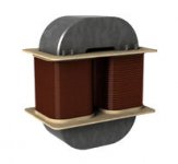
Not even with a C core transformer of this kind that offer the best isolation between primary and secondary:
Attachments
Last edited:
Of course, you had. No gear connected to the AC Mains can escape.
Just plug two of them across a AC socket strip with no ground. and, before to connect them together, measure the voltage between the output RCA ground of the first device and input RCA ground of the other with a high impedance voltmeter.
Not even with a C core transformer of this kind that offer the best isolation between primary and secondary:
I didn't want to imply there is no measurable/detectable leakage at all. Just not causing any issues I hear. In USA, we have leakage limits in electronic gear and it must meet it and/or UL in this regard. And many gear now have only 2 wire ac input -- no third ground pin and those are double isolated and very low leakage by design...... minimizing grnd loop potentials with other gear.
Here are two instruments I have to check on leakage ---> If I have a leakage issue, I will know it and where and how much etc.


I just measured a DAC and a receiver (2 yrs old)...... no leakage measured --- needle doesn't move at all. ... must be on the order of less than a microAmp. Both have 2 wire cords.
Now LP RIAA or long microphone runs etc could and do sometimes have issues..... But I haven't had an LP system in many many years... hum was sometimes an issue with phono IIRC. But even then I was able to reduce it to not be an issue --- still without Bal ips.THx-RNMarsh
Last edited:
I believe it is not a noise we can hear, like a hum or a buzz. It seams to affect the "clarity" of the signal. IMD products ?Just not causing any issues I can hear.
Each time I compared the same gear Battery powered VS AC powered, the difference was obvious.
Reason why I'm a little paranoid on the subject ?
Last edited:
TT --- There are many issues you could have. I always filter my ac lines to be very clean anyway.
Note also.... mechanical construction limitations of balanced cables or even twisted pair balanced wiring does not allow better symmetry than 1 percent. -40dB is typical no matter what the CMR of your DUT measures.
Unless, your DUT's CMR is causing distortion, a really high DUT number, in practice, isn't all that important in today's typical home audio situation/application.
If you have issues from ac power lines, ground loops, induced voltages/currents etc... fix it.
THx-RNMarsh
Last edited:
Richard, I'm not talking from my home's equipment but from my experinence in a lot of various audio facilities.TT --- There are many issues you could have. I always filter my ac lines to be very clean anyway.
If you have issues from ac power lines, ground loops, induced voltages/currents etc... fix it.
i just wanted to explain why the pro world is still using symmetry (with > 60db CMR). Lot with floating transformers
If i remember well, the couple SSM2141/42 offer 90dB. Don't remember the THAT performances.
keantoken, about SMPS, I believe this loop problem is, on the contrary, minimized because less leakage with the little trasfo they use and better isolation because the active device before-it. While rejecting 100kHz is not such a problem with the bandwidth of the actual equipment we use.Do you have SMPS in any of your equipment? 100KHz is more likely to get through isolation and cause problems.
dear Bob, I had a question on another thread...
Gotten one of latest China-made amplifier; uses pre-amp NE5532 follow-into Class D TPA3250. This FX502Spro is configured as Stereo BTL differential input, though I like to use it as single speaker mono-block, but had no idea how to mod to PBTL.
So let's say I use only 1 channel: ie. feeding audio into L-channel input, how to avoid possible damage how should I deal with unused R-channel?
Should I:
Short R-channel input, leave the R-output unconnected/open?
Or some suggested:
R-channel input to ground through a cap, and 8R 1W Load resistor at output to due with any picking up noise during amplification(unloaded output could end-up destroying output filter caps). As that amp is still switching so filters still have to filter?
Looking for 2nd opinion... thks.
Last edited:
Thank you for the detailed answer and large amount of useful hints.... The input to a 2T Miller-compensated VAS can look like a fairly low impedance, so here is an instance where one needs to watch out. ...
In a current design, I observed a similar issue when simulating the internal gain of a Darlington VAS with Miller compensation. At the input sits a 2T feedback current source that I had checked for 60 degrees of phase margin. Trying to make the VAS margins reliable, I always got "inexplicable" changes when e.g. swapping between your BC5xx models and others, and the phase behaviour generally looked "strange". Finally it turned out, that the vicinity of cross over frequencies in current source and VAS led to these strange results. Radical reduction of cross over frequency in the current source solved the problem; VAS loop characteristics now are acceptable and stable (at least in simulation and for the taste of a hobbyist ;-).
Cheers,
Matthias
Last edited:
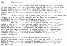
Our friend Ian Hegglun pointed me toward a relevant AES paper "Common mode distortion in differential stages" (preprint # 1742).
I am not allowed to post the whole paper (you can purchase it at the AES webstore) but attached is the conclusion. Supported by extensive measurements.
Jan
I am not allowed to post the whole paper (you can purchase it at the AES webstore) but attached is the conclusion. Supported by extensive measurements.
Jan
Attachments
Our friend Ian Hegglun pointed me toward a relevant AES paper "Common mode distortion in differential stages" (preprint # 1742).
I am not allowed to post the whole paper (you can purchase it at the AES webstore) but attached is the conclusion. Supported by extensive measurements.
Jan
Makes total sense
.Cheers,
Bob
Our friend Ian Hegglun pointed me toward a relevant AES paper "Common mode distortion in differential stages" (preprint # 1742).
I am not allowed to post the whole paper (you can purchase it at the AES webstore) but attached is the conclusion. Supported by extensive measurements.
Jan
Hi Mr. Didden
Yes, that paper makes sense.
BTW: As far as I can remember it is written by Terje Sandstrøm, and it is nearly 40 years since he wrote that paper.
I guess that you remember Electrocompaniet and their "Otala" amplifier?
Terje was one of the key people in the development of the classic Electrocompaniet 25W "Otala" amplifier.
All the best
Reodor
Yes I am aware. To be honest, when you look in the Elektrocompaniet history you see that very quickly they made substantial changes to the original Otala circuitry because 'it made it sound better'. More gain, more feedback...
Jan
Yes I am aware. To be honest, when you look in the Elektrocompaniet history you see that very quickly they made substantial changes to the original Otala circuitry because 'it made it sound better'. More gain, more feedback...
Jan
They did not make "substantial changes to the original Otala circuitry"
More gain, more feedback is correct.
BTW: It was done before the first exhibition.
That was not the point.
All the best
Reodor
Our friend Ian Hegglun pointed me toward a relevant AES paper "Common mode distortion in differential stages" (preprint # 1742).
Jan
Yes and since if not before.... transistor current sources have been used. cascoding the current source can improve it with higher Zo.
All of which is done in the better DIYAudio designs. IIRC -- compared to fet-fet or bjt-bjt, Very good current sources can be made with fet-bjt combo.
... Staying with just diff ips.
THx-RNMarsh
Got Bass? YouTube
Last edited:
Seems not any major issue since VAS compensation capacitance is small and usually degenerated with 100 ohm series resistor, thus impedance converge to this value. Anyway JFET sources act as a virtual ground so lowest loading impedance for the source is 1 k in parallel to 10 k ie. some 900 ohms, easy task for any correctly designed preamp.LazyCat's CFA Jfet input is interesting. I've considered it, but it's very difficult to reduce the input capacitance to VFA levels. After all, the input current must drive the VAS compensation through the Jfet sources. Used in inverting mode these currents don't load the input, but they can still be troublesome in the feedback network.
Although JFET input pair in common gate configuration has low input impedance in such inverting input amplifier case this is even preferable as they already represent virtual ground node. Side benefits of this design are very low input noise and enormous bandwidth, so nothing less than idea worthwhile to try.
- Home
- Amplifiers
- Solid State
- Bob Cordell's Power amplifier book