I'm sorry,
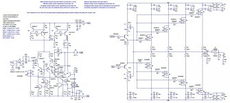
I've posted two pictures of the same circuit.
This is the one with cascoded VAS, I think I have lower THD1 because I'm using a BC550C (when using the cascode) as the main VAS transistor, which has lower noise/distortion figures. But as the cascoded beta enhanced VAS can be unstable, I think I'm going for the beta enhanced VAS like mcd99uk suggested.
I'm sorry for talking about my project in this thread, I only want to know how to evaluate local stability. Can you help me?
Best regards,
Daniel
Attachments
Last edited:
Minor loop stability is something I'm struggling with too. I have figured that the tian probe needs to used but can't fathom how to isolate the loops I want to test.
I find it effective to draw a simple block level schematic of the circuit to work out exactly what loop you want to probe. It's easier to be think clearly at this level about what you want to do.
Then the trick is to think about how to correctly place the Tian probe in the LTSpice ASC to examine that specific loop.
Correct placement means you should not have to "isolate" the loop with enormous inductors or capacitors, their use is both inaccurate and also prone to actual mistakes.
The Tian probe itself calculates and allows for forward and back transmission, so placement rather than attempted isolation is the key.
Is that helpful or too "hand wavy"?
Theoretically Tian has a minor omission, corrected in the Middlebrook "General Feedback Theorem", but I have never seen an audio amp where the omitted term was relevant.
Best wishes
David
Last edited:
The Tian probe...allows for forward and back transmission...
This is actually untrue. I discovered this when I used Rosenstark's method and compared its results with those obtained with the so-called "Tian" probe in determining minor-loop transmission of an amplifier. The results were identical.
Since Rosenstark's method (a derivative of Middlebrook's succesive determination of loop transmission) definitely doesn't account for reverse transmission, and gave identical results as the "Tian" probe, it is clear that the the later also doesn't accomodate reverse transmission, which in this case really was forward transmision through the Miller feedback capacitor which gives rise to the RHP zero.
Last edited:
I find it effective to draw a simple block level schematic of the circuit to work out exactly what loop you want to probe. It's easier to be think clearly at this level about what you want to do.
Then the trick is to think about how to correctly place the Tian probe in the LTSpice ASC to examine that specific loop.
Correct placement means you should not have to "isolate" the loop with enormous inductors or capacitors, their use is both inaccurate and also prone to actual mistakes.
The Tian probe itself calculates and allows for forward and back transmission, so placement rather than attempted isolation is the key.
Is that helpful or too "hand wavy"?
Theoretically Tian has a minor omission, corrected in the Middlebrook "General Feedback Theorem", but I have never seen an audio amp where the omitted term was relevant.
Best wishes
David
Hi David,
I shall try this method of drawing a block diagram. It may help starting at the top level.
I am beginning to see these circuits these days as a mass of meshes. (Yes, I am slowly digesting the bode text you suggested studying) The trouble is I see loops affecting other loops and this is where my confusion starts.
I figured placement was important but where to place it is also something that confuses me. Even trying to analyse TMC is problematic.
Thank you for any help.
Paul
Care to post an example with significant 'reverse transmission' and details of how you did this?This is actually untrue. I discovered this when I used Rosenstark's method and compared its results with those obtained with the so-called "Tian" probe in determining minor-loop transmission of an amplifier. The results were identical.
Since Rosenstark's method (a derivative of Middlebrook's succesive determination of loop transmission) definitely doesn't account for reverse transmission, and gave identical results as the "Tian" probe, it is clear that the the later also doesn't accomodate reverse transmission, which in this case really was forward transmision through the Miller feedback capacitor which gives rise to the RHP zero.
This is actually untrue. I discovered this when I used Rosenstark's method and compared its results with those obtained with the so-called "Tian" probe in determining minor-loop transmission of an amplifier. The results were identical.
The Tian et al paper is in IEEE Circuits and Devices Jan. 2001 pp 31- 41 and explains how forward and reverse transmission are incorporated.
If you have found an error then please post the details, I would be very interested to learn more.
Best wishes
David
... The trouble is I see loops affecting other loops and this is where my confusion starts.
Bode himself understood this problem and solved it with the concept of Return Ratio.
This is a property defined at each node.
It is equivalent to Loop Gain for the case of a simple loop but is cleverly independent of any assumptions about loop structure, so is still clearly defined even if the loops are tangled.
I figured placement was important but where to place it is also something that confuses me. Even trying to analyse TMC is problematic.
Thank you for any help.
I have a few posts over in the TPC vs TMC vs Cherry thread that are relevant.
I hope they help some more.
Best wishes
David
Off topic request...
Has anyone used a MAC and LTspice ? How do you get all the options and control panel to show ?
If so can you help here,
http://www.diyaudio.com/forums/powe...uild-linear-12v-power-supply.html#post3698609
Has anyone used a MAC and LTspice ? How do you get all the options and control panel to show ?
If so can you help here,
http://www.diyaudio.com/forums/powe...uild-linear-12v-power-supply.html#post3698609
Same question -- what if it was a circuit topology without gnfb to - input? There is still distorted signal at input to VAS when using real speaker for load.. Low level, but it is there. Which OPS will minimize it under that condition (not thru the gnfb or - input port).
Thx-RNMarsh
Thx-RNMarsh
Same question -- what if it was a circuit topology without gnfb to - input? There is still distorted signal at input to VAS when using real speaker for load.. Low level, but it is there. Which OPS will minimize it under that condition (not thru the gnfb or - input port).
Thx-RNMarsh
Whatever OPS that has the lowest Zout and flattest Zout with load & freq (no nfb) would minimize this, no?
Jan
Bob,
What is the mechanism which allows an oscillator put on the speaker output terminals to get back to the VAS input? [besides low output Z]
And, second, what is the best way to minimize (attenuate?) this? Is it thru greater isolation and how?
Thx-RNMarsh
Hi Richard,
Sorry to be slow in getting back to you on this. I assume you're talking about signals that get somehow injected onto the output terminals getting back to the VAS, such as EMI or speaker EMF. I'm also guessing that you are primarily thinking about the path via the NFB loop and through the input stage. This is the concern most often talked about, and it is often even more in the context of disturbing the input stage. I believe that JFET input stages are superior in being resistant to these effects.
Anyway, in most cases the mechanism is through the NFB, especially if there is a lead capacitor across the feedback resistor. Also, most often we are talking about stuff getting fed back at higher frequencies.
It is true that there are other ways in which EMI injected at the output can get possibly do bad things, and possibly get back to the VAS. For example, the output stage has very finite ability to isolate the VAS output node from the amplifier output due to the finite current gain of the output stage. Triples most certainly help this a lot at audio frequencies, but are also limited in current gain and isolation at high frequencies.
In principle, it is also possible that some stuff at the amplifier output can make its way back to the VAS via the compensation capacitors in a TMC arrangement through the TMC resistor.
Finally, and not directly involving the VAS, HF currents flowing into the output of the amplifier meet up with PN junctions in the output transistors, where there exists the possibility of some intermodulation.
Admittedly, all of these effects are subject to a matter of degree, and some may be very small. In my book I discuss some arrangements where one or more RF tones are injected at the output of the amplifier to evaluate an amplifier's resistance to such effects.
The output network, consisting of the series L-R coil and R-C Zobels on either or both sides of the L-R network will mitigate some HF stuff getting back into the amplifier to some extent, and can only help. Damping provided on the output node by these networks helps, but one also needs to realize that the small-value resistor in parallel with the coil (often 2-5 ohms) will limit the amount of HF attenuation provided by the coil.
I view the combination of the speaker cable and the loudspeaker as a big potential antenna, and touch on these concerns in my book.
I hope I have addressed the right question here and hope that it helps.
Cheers,
Bob
By Bob Cordell -especially if there is a lead capacitor across the feedback resistor
Could this be why most vintage amp's using lead compensation also add
a resistor in series with the lead capacitor ?
OS
Could this be why most vintage amp's using lead compensation also add
a resistor in series with the lead capacitor ?
OS
Not necessarily. In my understanding, the resistor in series with the lead capacitor is to add a pole subsequent to the zero so as to limit the amount of effect that the lead capacitor has at much higher frequencies. This would be for stability reasons. Even with no resistor in series with the lead capacitor, there is a pole in the feedback network function, so the resistor actually just moves a pole that was already there to a lower frequency.
However, it is true that the series resistor will create some attenuation at RF frequencies that would not have been there without the resistor, so it can be said that the resistor will somewhat mitigate such effects. I just don't think that was the reason the designers put it there.
Cheers,
Bob
To test this could you inject an .AC analysis into the OP after
the output inductor and just monitor the NFB loop ?
A crude example below (AM - Ghz)...
PS - I don't see how you could get 1V RF , unless your neighbor was a ham
operator .
.
OS
the output inductor and just monitor the NFB loop ?
A crude example below (AM - Ghz)...
PS - I don't see how you could get 1V RF , unless your neighbor was a ham
operator
.OS
Attachments
Last edited:
Hi Richard,
.......
.....
...
..... I hope I have addressed the right question here and hope that it helps.
Cheers,
Bob
Thx, Bob,
Yes, most were answered.
-RNMarsh
My comment on Cordell's fig16.7
http://www.diyaudio.com/forums/soli...honey-badger-build-thread-16.html#post3731769
I have added a comment about Power Supplies relating to the advice in section 16.4
Some may want to comment on my post and views contained therein.
http://www.diyaudio.com/forums/soli...honey-badger-build-thread-16.html#post3731769
I have added a comment about Power Supplies relating to the advice in section 16.4
Some may want to comment on my post and views contained therein.
Last edited:
- Home
- Amplifiers
- Solid State
- Bob Cordell's Power amplifier book