Hi Bob,
You might consider including calculations for your SOA protection circuits in your second edition. This would aid folk in designing their own protection circuits.
Secondly, you could show how designers may confirm and tweak their calculated SOA protection component values in SPICE, as well as simulating the effect of ambient temperature on the protection locus.
All this information is available in an article you can have by sending me mail.
Hi Mike,
This is an excellent idea. Thanks for sending me that article. Simulating protection circuits in SPICE makes sense. I'm also tempted to discuss some real-world lab tests that can safely exercise protection circuits. A long time ago I created a nasty load that included an inductor, and I was able to provoke the really nasty protection spikes that often occur (we used to call those "tweeter eaters"). This same sort of thing could easily be demonstrated in a SPICE simulation.
We always need protection, but fortunately nowadays we have more SOA and can set the triggering thresholds higher so the protection circuits come into play much less often.
Cheers,
Bob
> fortunately nowadays we have more SOA
True, boys as well as girls.But fortunately? No!
(in Dutch SOA means: Seksueel Overdraagbare Aandoening. Translated: STD, sexually transmissible disease)
Cheers,
E.
I never was very good with foreign language
.Those TLA's get me every time (Three Letter Acronym).
Cheers,
Bob
SOA etc
I'm really a speaker man and would like to say something about speaker loads.
Firstly, the Otala test signal is absolute rubbish and from fairy-tale land .. like his zillion V/us slew rates.
__________________
I've only found one real life case where the current demand of a speaker exceeds what you'd expect from its impedance curve.
A bass unit usually has a large voice coil with many turns and a hunk of steel (the polepiec) in the middle. This gives it a large Inductance and hence impedance. However, as the coil moves, the hunk of steel may also move out of the coil and the Inductance (and Impedance) drops dramatically. The current through the coil then increases which tends to push the coil further out of the gap.
This is an unstable phenomena and the coil jumps out of the gap with nasty consequences.
There are various 'cures' but a simple dodge is to let the suspension limit as the coil reaches its 'linear' Xmax limits. Rather non-intuitively, distortion near the limit is reduced when you do this.
The bass units that jump out of the gap are from makers who believe a static 'linear' compliance gives dynamic linearity.
I think Don Barlow did an AES paper on this but it might have been an internal Engineering Memo.
Apart from this, the current / SOA demands can be predicted from the speakers complex impedance.
_______________
From the SOA protection point of view, double slope or even high single slope protection was prone to what we used to call 'snap crackle pop' protection cos this was what it sounded like when triggered ... either by reactive loads or the above. (Your 'nasty protection spikes' are part of this)
Dem we de days of serious double slope SOA protection in big (and small) amps.
Simple current limiting was the 'best sounding' protection when triggered.
But as you say, since the late 80's we have much better devices available. IME, a 50W @8R amp can get away with simple fuses in the PSU leads.
______________________
PTC 'fuses' (eg RXE075 PTC Fuses - Speaker Protection - Jaycar Electronics) can be very closely matched to speakers (and amps?). Unfortunately, when triggered and automatically reset, they take some time to regain their Low resistance.
In most cases, this leads to less than a fraction of a dB of power loss but the marketing department always complains.
Yes please Bob.I'm also tempted to discuss some real-world lab tests that can safely exercise protection circuits. A long time ago I created a nasty load that included an inductor, and I was able to provoke the really nasty protection spikes that often occur (we used to call those "tweeter eaters"). This same sort of thing could easily be demonstrated in a SPICE simulation.
We always need protection, but fortunately nowadays we have more SOA and can set the triggering thresholds higher so the protection circuits come into play much less often.
I'm really a speaker man and would like to say something about speaker loads.
Firstly, the Otala test signal is absolute rubbish and from fairy-tale land .. like his zillion V/us slew rates.
__________________
I've only found one real life case where the current demand of a speaker exceeds what you'd expect from its impedance curve.
A bass unit usually has a large voice coil with many turns and a hunk of steel (the polepiec) in the middle. This gives it a large Inductance and hence impedance. However, as the coil moves, the hunk of steel may also move out of the coil and the Inductance (and Impedance) drops dramatically. The current through the coil then increases which tends to push the coil further out of the gap.
This is an unstable phenomena and the coil jumps out of the gap with nasty consequences.
There are various 'cures' but a simple dodge is to let the suspension limit as the coil reaches its 'linear' Xmax limits. Rather non-intuitively, distortion near the limit is reduced when you do this.
The bass units that jump out of the gap are from makers who believe a static 'linear' compliance gives dynamic linearity.
I think Don Barlow did an AES paper on this but it might have been an internal Engineering Memo.
Apart from this, the current / SOA demands can be predicted from the speakers complex impedance.
_______________
From the SOA protection point of view, double slope or even high single slope protection was prone to what we used to call 'snap crackle pop' protection cos this was what it sounded like when triggered ... either by reactive loads or the above. (Your 'nasty protection spikes' are part of this)
Dem we de days of serious double slope SOA protection in big (and small) amps.
Simple current limiting was the 'best sounding' protection when triggered.
But as you say, since the late 80's we have much better devices available. IME, a 50W @8R amp can get away with simple fuses in the PSU leads.
______________________
PTC 'fuses' (eg RXE075 PTC Fuses - Speaker Protection - Jaycar Electronics) can be very closely matched to speakers (and amps?). Unfortunately, when triggered and automatically reset, they take some time to regain their Low resistance.
In most cases, this leads to less than a fraction of a dB of power loss but the marketing department always complains.
Last edited:
This is an unstable phenomena and the coil jumps out of the gap with nasty consequences.
JBL tech. notes mention this. I always assumed it was their research.
Who first published?
Had not considered the implications for the amp.
Best wishes
David
Don Barlow did this work in the 70's. I'm sad his name doesn't even appear in AES lib.JBL tech. notes mention this. I always assumed it was their research.
Who first published?
He's best known for the LEAK sandwich speaker but he was a polymath who made many contributions to the state of the art in speakers, turntables and pickups.
I was privileged to have worked with him in his last days at LEAK/Wharfedale.
[edit]Dr. Barlow appears as DA Barlow. I note a 1991 JBL paper credits him for something. So do Mills & Hawkesford in 1986.[/edit]
Last edited:
.. but the amp must be designed to be nice to the speaker when it loses a rail.... since the late 80's we have much better devices available. IME, a 50W @8R amp can get away with simple fuses in the PSU leads.
Yes please Bob.
I'm really a speaker man and would like to say something about speaker loads.
Firstly, the Otala test signal is absolute rubbish and from fairy-tale land .. like his zillion V/us slew rates.
__________________
I've only found one real life case where the current demand of a speaker exceeds what you'd expect from its impedance curve.
A bass unit usually has a large voice coil with many turns and a hunk of steel (the polepiec) in the middle. This gives it a large Inductance and hence impedance. However, as the coil moves, the hunk of steel may also move out of the coil and the Inductance (and Impedance) drops dramatically. The current through the coil then increases which tends to push the coil further out of the gap.
This is an unstable phenomena and the coil jumps out of the gap with nasty consequences.
There are various 'cures' but a simple dodge is to let the suspension limit as the coil reaches its 'linear' Xmax limits. Rather non-intuitively, distortion near the limit is reduced when you do this.
The bass units that jump out of the gap are from makers who believe a static 'linear' compliance gives dynamic linearity.
I think Don Barlow did an AES paper on this but it might have been an internal Engineering Memo.
Apart from this, the current / SOA demands can be predicted from the speakers complex impedance.
_______________
From the SOA protection point of view, double slope or even high single slope protection was prone to what we used to call 'snap crackle pop' protection cos this was what it sounded like when triggered ... either by reactive loads or the above. (Your 'nasty protection spikes' are part of this)
Dem we de days of serious double slope SOA protection in big (and small) amps.
Simple current limiting was the 'best sounding' protection when triggered.
But as you say, since the late 80's we have much better devices available. IME, a 50W @8R amp can get away with simple fuses in the PSU leads.
______________________
PTC 'fuses' (eg RXE075 PTC Fuses - Speaker Protection - Jaycar Electronics) can be very closely matched to speakers (and amps?). Unfortunately, when triggered and automatically reset, they take some time to regain their Low resistance.
In most cases, this leads to less than a fraction of a dB of power loss but the marketing department always complains.
Hi kgrlee,
Thanks for this post. These are all excellent posts. I'm a "speaker guy" too, although I don't consider myself an expert on the electromechanical aspects of drivers. Your obervations about what happens to woofers when they are pushed to excessive excursion are very helpful.
Cheers,
Bob
LT1166
Hi Bob,
Reading your excellent book, I found something that might lead to confusion. It's about Miller compensation in conjunction with a LT1166, page 547..548. You wrote: "If the Miller capacitor is just connected to one end of the LT1166 dynamic bias spreader, distortion will result because this node contains the signal plus half the non-linear spreading voltage. Instead, Miller capacitors of equal value (C1 and C2) should be connected from each end of the bias spreader back to the input of the VAS. This will force the virtual center tap of the bias spreader to be the desired linear representation of the signal."
(last sentence underlined by me)
First, this is the best you can do. The text however, suggests that all non-linearities caused by the dynamic bias spreader are eliminated. Regrettably, this is not the case. The center tap lowers the distortion, but not completely. It's still higher compared to a fixed bias. Please, see also this post.
Perhaps you could elaborate on this subject in the next edition of your book.
Cheers,
E.
Reqeust for book
Hello Bob,
Enjoyed the book and looking forward to the new rev.
Would love to see a small section on how to add filtering to basic constant current sources to improve them. Have seen several variations in different schematics and would love some idea of what works best and perhaps what doesn't work as well.
Lots of CCS's in audio equipment. If adding filtration to them is easy and practical, would be a great mod method.
Regards,
Greg
Hi Bob,
Reading your excellent book, I found something that might lead to confusion. It's about Miller compensation in conjunction with a LT1166, page 547..548. You wrote: "If the Miller capacitor is just connected to one end of the LT1166 dynamic bias spreader, distortion will result because this node contains the signal plus half the non-linear spreading voltage. Instead, Miller capacitors of equal value (C1 and C2) should be connected from each end of the bias spreader back to the input of the VAS. This will force the virtual center tap of the bias spreader to be the desired linear representation of the signal."
(last sentence underlined by me)
First, this is the best you can do. The text however, suggests that all non-linearities caused by the dynamic bias spreader are eliminated. Regrettably, this is not the case. The center tap lowers the distortion, but not completely. It's still higher compared to a fixed bias. Please, see also this post.
Perhaps you could elaborate on this subject in the next edition of your book.
Cheers,
E.
Hi Edmond,
You make a good point, and this is a subject that can use more exploration and explanation. The amount of the additional distortion due to the dynamic bias spreader in the LT1166 needs to be evaluated more carefully by me. The LT1166 dynamic bias spreader actually makes the output stage a non-switching class A-B stage (what some people wrongly refer to a class A). Under the right conditions, this dynamic bias spreader action may reduce crossover distortion. I need to do more research on this. Thanks for bringing this up as a matter that needs more attention in the Second Edition.
Cheers,
Bob
Hello Bob,
Enjoyed the book and looking forward to the new rev.
Would love to see a small section on how to add filtering to basic constant current sources to improve them. Have seen several variations in different schematics and would love some idea of what works best and perhaps what doesn't work as well.
Lots of CCS's in audio equipment. If adding filtration to them is easy and practical, would be a great mod method.
Regards,
Greg
Hi Greg,
Thanks for your kind words about my book.
I'll be happy to include some suggestions on that. I'll note that, to some extent, since the output of a current source is ideally a current and a high impedance, the implication to filtering the output might imply a large inductor and be somewhat impractical. From this point of view, the CCS needs to be designed to be quiet in the first place. The implication here is that any reference used by the current source must be quiet and free of noise or ripple from the rail. A simple example here would be the placing of a capacitor across a green LED reference or placing a capacitor along the resistance that supplies current to the CCS reference. I also often place a decent-sized resistor in series with the output of a current source to provide some isolation at HF, such as when the CCS is used for the tail of an LTP.
Is this sort of thing what you had in mind, or did I miss the mark?
Speaking of there being lots of CCS in audio equipment, one must exercise caution in using many of the handy current-source ICs. Many of these have limitations on the allowable voltage slew rate of the signals that are made to appear across them. This may limit their applicability in some parts of circuits and/or require additional circuitry to isolate them from the voltage slew rates that may be present, such as using a cascode transistor.
Cheers,
Bob
CCS
Thank you Bob,
Yes, that is the stuff that would be of interest to myself and most likely others. How to add cap filtering to basic two transistor (or led biased) CCS's. Seems like just adding a cap across the v ref part of it would help some, but I rarely see anyone at all do that. Wondering if there is a reason they do not.
I have downloaded LTspice and hope to figure out how to use it at some point. Got a few things figured out, but a long way to go before I trust anything as results.
Regards,
Greg
filtering noise at a low Z point like right at a reference diode requires large C to make the filter corner frequency low
for noise it is much better to filter with a series R, C (to the right AC gnd for the circuit), the LP filter between the Vref and the regulating Q
can improve PSRR by splitting the reference's bias R and adding the filter C to the midpoint
for noise it is much better to filter with a series R, C (to the right AC gnd for the circuit), the LP filter between the Vref and the regulating Q
can improve PSRR by splitting the reference's bias R and adding the filter C to the midpoint
[..]
Seems like just adding a cap across the v ref part of it would help some, but I rarely see anyone at all do that. Wondering if there is a reason they do not.
[..]
Regards,
Greg
If the noise acts in common mode, no reason to remove it.
Cheers,
E.
CCS
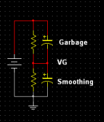
Wouldn't that transfer PS garbage into the circuit ? For eg, as in my screenie. If a Cap is placed across the top Res in a "Virtual" Ground application, it will do exacly that !
Or did you mean placing a Cap from the CCS to Ground ? Wouldn't that cause issues too though ?
Re post # 2713
Originally Posted by Bob Cordell
or placing a capacitor along the resistance that supplies current to the CCS reference.
Wouldn't that transfer PS garbage into the circuit ? For eg, as in my screenie. If a Cap is placed across the top Res in a "Virtual" Ground application, it will do exacly that !
Or did you mean placing a Cap from the CCS to Ground ? Wouldn't that cause issues too though ?
Attachments
yes a big part of engineering isn't just knowing a bunch of circuit techniques - its establishing quantifiable goals, knowing circuit sensitivity, when additional techniques are required - but also knowing when they wouldn't improve anything important to the final resultIf the noise acts in common mode, no reason to remove it.
when splitting the bias R, you only apply one cap - to create a low pass filter, with the C AC gnd appropriate for your circuit
Last edited:
Originally Posted by jcx
when splitting the bias R, you only apply one cap - to create a low pass filter, with the C AC gnd appropriate for your circuit
Hi, i presume you were responding to me ?
If so, i realise that
which is why i mentioned the Garbage transfer, & therefore is not good ! Which makes me ask, why BC was suggesting
?placing a capacitor along the resistance that supplies current to the CCS reference
Hopefully Bob will respond
Yes please Bob. This would be of great interest.Speaking of there being lots of CCS in audio equipment, one must exercise caution in using many of the handy current-source ICs. Many of these have limitations on the allowable voltage slew rate of the signals that are made to appear across them.
The slew limit is a new one to me. Are there other references or is this something you've discovered yourself?
And are they any SPICE models for these handy 2 terminal CCS which you trust? I thought most of them were simple JFETs with selected Idss.
- Home
- Amplifiers
- Solid State
- Bob Cordell's Power amplifier book