indeed
Hi
I find that since the bias for vertical mosfets is usually >150mA, allowing the system to be a bit overcompensating can buy a bit of extra stability with regard to dynamic tempco. Although the effect is small, the fets get a boost in Gm at a higher temperature.If the effect of overcompensation is slight, the bias can be kept within acceptable range, >100mA at maximum temperatures. Consequently, initial static bias may be a bit higher but since the devices and heatsink are cold it is of slight issue. I have had success in stablizing bias of vertical mosfets using a topology similar to the HEC Bob used, but I use small SMD devices as the error amplifiers, mounted on the PCB so as to be in contact with the drain pin close to the transistor package. Although there is a short distance of metal for the heat to traverse, it is not so effected by the time lag of the thermal insulator/heatsink. see pic from previous learning experience.
")
Hi CBS240,
This seems like a neat idea. I agree that a little bit of overcompensation is OK. Nice pic!
Cheers,
Bob
Hi Bob,
Well I've been having a great time playing with LTSpice, all thanks to your book, and I wondered... generally speaking, how well do you find circuits simulated with LTspice translate into real life circuits ?
I can see how easy it is to chase the minute details... for example changing a transistor type to eek that extra 0.0001% of something or other when perhaps realistically that all falls apart a little in a real build.
That was one question I have wondered over for a while, but I have encountered a bit of a puzzle with a simulation that makes me wonder all the more. (and I know the real answer is to go and build the thing)
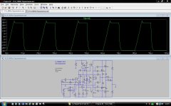
So I have a design in simulation that gives spectacularly bad results on slew rate (50Khz squarewave test) when using the MJE340C model as a VAS. It's that slow you would need to send it a postcard with advance warning a voltage change was coming. However if I swap it for pretty much anything else the results are more in line with what I might have expected. The VAS current is highish by design at around 25ma.
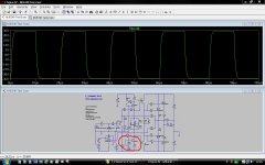
If I modify the drive to the VAS as shown in red then it works OK although at the expense of other aspects of the design suffering.
What parameter/s of the transistor model might be causing this slew limiting effect ? and do you think this a real effect if it were built for real using an MJE340. Your 2SC3503C model on the other hand gives a very good result in simulation.
Well I've been having a great time playing with LTSpice, all thanks to your book, and I wondered... generally speaking, how well do you find circuits simulated with LTspice translate into real life circuits ?
I can see how easy it is to chase the minute details... for example changing a transistor type to eek that extra 0.0001% of something or other when perhaps realistically that all falls apart a little in a real build.
That was one question I have wondered over for a while, but I have encountered a bit of a puzzle with a simulation that makes me wonder all the more. (and I know the real answer is to go and build the thing
) So I have a design in simulation that gives spectacularly bad results on slew rate (50Khz squarewave test) when using the MJE340C model as a VAS. It's that slow you would need to send it a postcard with advance warning a voltage change was coming. However if I swap it for pretty much anything else the results are more in line with what I might have expected. The VAS current is highish by design at around 25ma.
If I modify the drive to the VAS as shown in red then it works OK although at the expense of other aspects of the design suffering.
What parameter/s of the transistor model might be causing this slew limiting effect ? and do you think this a real effect if it were built for real using an MJE340. Your 2SC3503C model on the other hand gives a very good result in simulation.
Attachments
Mooly have a look at CJE and CJC. Its real.
Here is a useful program that all could use to verify their spice models with datasheets.
Wolfram Demonstrations Project
Here is a useful program that all could use to verify their spice models with datasheets.
Wolfram Demonstrations Project
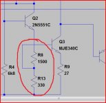
It appears the base feed into the 340 does not like the 3k9 as source resistance.
Changing that to 330r sorts the RC slew limiter.
But, why run the preceding EF with an Ie~0.15mA. simply reducing the 3k9 emitter resistor to somewhere between 99r and 1001r would be more sensible.
Changing that to 330r sorts the RC slew limiter.
But, why run the preceding EF with an Ie~0.15mA. simply reducing the 3k9 emitter resistor to somewhere between 99r and 1001r would be more sensible.
Mooly have a look at CJE and CJC. Its real.
Thanks homemodder, that's spot on.
I just tried adding a little junction capacitance to the 2SC3503 and that's it.
Couldn't see it for looking
Thanks for the link too.
It appears the base feed into the 340 does not like the 3k9 as source resistance.
Changing that to 330r sorts the RC slew limiter.
But, why run the preceding EF with an Ie~0.15mA. simply reducing the 3k9 emitter resistor to somewhere between 99r and 1001r would be more sensible.
It's me Andrew... mental block. I couldn't believe the MJE340 would be so "bad" (not the right word but you know what I mean) in real life and I couldn't work away from that thought.
Sheesh, and when I think of all the 1000's of line driver and PSU faults I have worked on where slow turn off has been the trouble. Inexcusable
Hi Bob,
Well I've been having a great time playing with LTSpice, all thanks to your book, and I wondered... generally speaking, how well do you find circuits simulated with LTspice translate into real life circuits ?
I can see how easy it is to chase the minute details... for example changing a transistor type to eek that extra 0.0001% of something or other when perhaps realistically that all falls apart a little in a real build.
That was one question I have wondered over for a while, but I have encountered a bit of a puzzle with a simulation that makes me wonder all the more. (and I know the real answer is to go and build the thing
So I have a design in simulation that gives spectacularly bad results on slew rate (50Khz squarewave test) when using the MJE340C model as a VAS. It's that slow you would need to send it a postcard with advance warning a voltage change was coming. However if I swap it for pretty much anything else the results are more in line with what I might have expected. The VAS current is highish by design at around 25ma.
If I modify the drive to the VAS as shown in red then it works OK although at the expense of other aspects of the design suffering.
What parameter/s of the transistor model might be causing this slew limiting effect ? and do you think this a real effect if it were built for real using an MJE340. Your 2SC3503C model on the other hand gives a very good result in simulation.
Hi Mooly,
I'm sorry I did not get back to you sooner. It looks like you have already gotten some good answers. When I saw your post I looked at my MJE340C model, thinking it might have something wrong with it. The CJC is particularly high for this part; so high that I went looking at the datasheets for it and commercial SPICE models for it. Most of the datasheets for this device are among the most awful I have ever seen. I did, however, convince myself that the CJC is fairy real and that my Tf, reflective of ft is about right. For my model, at 10V and 10mA, Cbc = 59 pF and ft = 19 MHz. I was still surprized at how different the results were that you got between it and some other transistors.
This all underlines how important SPICE simulation is and how important reasonably accurate transistor models are. Two of the biggest reasons I use SPICE are: 1) I want to avoid surprizes when I build the circuit; 2) I want to be able to quickly play with different circuit architectures and component values. I often find a fundamentally better circuit architecture or better set of component values after only a few simulations. I find the insight to be incredibly valuable. I especially never want surprizes with the DC values. I have also found SPICE to be quite reliable in predicting instabilities that are not a result of real-world implementation parastics that may not be modeled. If a circuit shows signs of peaking or instability in SPICE, you are very likely to have trouble in the build.
With respect to distortion, SPICE gives useful information (again, limited by the accuracy of the transistor models) in a relative sense, but if I come within a factor of two of real-world measured distortion I feel good. I don't set my expectations high for distortion correlation, but I do find SPICE valuable in evaluating topologies for distortion creation.
Class A small-signal distortion that depends largely on the exponential Vbe characteristic comes in pretty well. That which depends on beta nonlinearity also comes in fairly well if the transistor models do a decent job of modeling beta. Distortion dependent on Early effect comes in less well, and the way SPICE models Early effect is not that great - and VAF parameters in models are often all over the place. Distortion in class AB output stages resulting from static or dynamic crossover distortion is less dependable.
Power MOSFETs generally need to have decent EKV modles (rare) for good modeling of class AB output stage distortion.
My philosophy is that the IPS/VAS can and should be good enough to the point that the output stage distortion is what is left dominating the overall distortion of the amplifier.
I hope this helps.
Cheers,
Bob
My philosophy is that the IPS/VAS can and should be good enough to the point that the output stage distortion is what is left dominating the overall distortion of the amplifier.
I agree. And on that note, small signal devices are more 'ideal' if one had to define a real world ideal transistor. Using a local loop around the output stage and drivers within the global loop ala Cherry or Hawksford can help to reduce the distortion of the output stage isolating those distortion components, some of which are high order, so they do not contaminate the global loop, which is more limited in BW. In addition to aiding PSR, since the local loop is a closed loop, the current gain is higher allowing a lower bias VAS using smaller, small signal components. Incidentally I find those little SMD thick film resistors to be quite quiet and well worth the few pennies they cost.
Thanks for the detailed reply Bob,
I'm quite a long way off creating models or altering models at the moment, it's all very much an (enjoyable) learning adventure at present.
I'm beginning to see that decent models are absolutely vital to achieving realistic results and distortion modelling is one aspect that is really beginning to intrigue me with Spice. I found trying something a bit unlikely such as using a medium power device (2SC3503) as an input stage can throw up surprising results. Heck I even tried lateral and hexfets for the input... and it wasn't all bad, that's for sure. In fact I'm amazed at some of the figures I'm seeing in general, sub 0.00015% THD. All intriguing stuff.
Next up for me is to try and copy your "A weighted filter" from your examples and insert and include that into my simulations.
Thanks again, and the book is proving invaluable help for all this. I'm sure without it I'd still be staring at a "new schematic" screen and wondering where to begin.
Mooly, figures like that with your circuit at 1 Khz is quite possible but what you should also look at is at how other parameters affect the design as well. For instance VAF which is early voltage is also very important. You could find a part say with very low capacitances but low early voltage, this would cause low high frequency distortion (20khz) but much higher distortion at 1 khz and lower frequencies. Rule of thumb, capacitances effect mostly high frequency operation while early effect the low frequencies, this is very important especially when there are large voltage swings present ie vas. For instance using a 2n5551 as vas in your circuit should show lower distortion at 20khz then 2sa3503 but because of the laters much higher early voltage it will outperform the first when low frequencies come into play. If this doesnt show in the simulation the models are defective. In your case you were wise to look at the square wave responses as the mje340 could show lowish distortion at lower frequencies due to its highish early voltage but perform terribly at high frequencies ie the mje will for instance outperform a bd140 at low frequency but at 20khz the bd will be superior. The point in frequency where this interaction takes place is not always clear so one needs to check THD at low and high frequencies. This interactions also effects the harmonic structure but instead of a short explanation Ill refer to a paper below where real life examples are shown and you can deduce from there. Harmonic structures can be manipulated to a certain degree if this is your type of thing with just the choice of component used.
This is a subject that should appear in audio amplifier books although it hasnt yet but samuel groner has shown and discussed these effects in his paper shown here on DIYaudio. Its very informative and a must read on this subject and some others.
This is a subject that should appear in audio amplifier books although it hasnt yet but samuel groner has shown and discussed these effects in his paper shown here on DIYaudio. Its very informative and a must read on this subject and some others.
homemodder and everyone else,
I'll put all the files over to a new thread where (I hope) you can run them and see. The MJE340 actually came out the best by a whisker for distortion tests at 1 and 20Khz. The harmonic content on the FFT plot is something I have looked at closely from the start for all variations of the design.
With the 2SC3503 as a VAS is giving the following THD figures,
0.00018% 1Khz @ 1watt
0.0020% 1Khz @ 90 watts
0.00042% 20Khz @ 1 watt
0.005% 20Khz @ 90watts
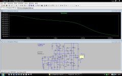
My experiment with the A weighted filter (my learning task for today with LTspice) gives exceptional results... SNR around 190db. That can't be right although the figure before the filter is reasonable at some 237uV total noise. I copied the filter from figure 19.7 (the downloaded files from Bobs site) and pasted the .sub and .asy files into my amp file. So I don't know what (assuming it has) has gone wrong there.
My noise is a funny a funny shape too (comparing with fig 19.7)
Edit... and I have just seen why Doh or DOH
I'll put all the files over to a new thread where (I hope) you can run them and see. The MJE340 actually came out the best by a whisker for distortion tests at 1 and 20Khz. The harmonic content on the FFT plot is something I have looked at closely from the start for all variations of the design.
With the 2SC3503 as a VAS is giving the following THD figures,
0.00018% 1Khz @ 1watt
0.0020% 1Khz @ 90 watts
0.00042% 20Khz @ 1 watt
0.005% 20Khz @ 90watts
My experiment with the A weighted filter (my learning task for today with LTspice) gives exceptional results... SNR around 190db. That can't be right although the figure before the filter is reasonable at some 237uV total noise. I copied the filter from figure 19.7 (the downloaded files from Bobs site) and pasted the .sub and .asy files into my amp file. So I don't know what (assuming it has) has gone wrong there.
My noise is a funny a funny shape too (comparing with fig 19.7)
Edit... and I have just seen why
Doh or DOHAttachments
Mooly, figures like that with your circuit at 1 Khz is quite possible but what you should also look at is at how other parameters affect the design as well. For instance VAF which is early voltage is also very important. You could find a part say with very low capacitances but low early voltage, this would cause low high frequency distortion (20khz) but much higher distortion at 1 khz and lower frequencies. Rule of thumb, capacitances effect mostly high frequency operation while early effect the low frequencies, this is very important especially when there are large voltage swings present ie vas. For instance using a 2n5551 as vas in your circuit should show lower distortion at 20khz then 2sa3503 but because of the laters much higher early voltage it will outperform the first when low frequencies come into play. If this doesnt show in the simulation the models are defective. In your case you were wise to look at the square wave responses as the mje340 could show lowish distortion at lower frequencies due to its highish early voltage but perform terribly at high frequencies ie the mje will for instance outperform a bd140 at low frequency but at 20khz the bd will be superior. The point in frequency where this interaction takes place is not always clear so one needs to check THD at low and high frequencies. This interactions also effects the harmonic structure but instead of a short explanation Ill refer to a paper below where real life examples are shown and you can deduce from there. Harmonic structures can be manipulated to a certain degree if this is your type of thing with just the choice of component used.
This is a subject that should appear in audio amplifier books although it hasnt yet but samuel groner has shown and discussed these effects in his paper shown here on DIYaudio. Its very informative and a must read on this subject and some others.
Hi homemodder,
Your comments about Early Effect are right on target. I did cover Early Effect in my book, but perhaps I could have covered it in even more depth. Check out pages 19, 128 and 147.
I should, however, have been more explicit about your correct insight about Early Effect often being more important at lower frequencies, like 1 kHz, and nonlinear Ccb being more important at higher frequencies like 20 kHz. These effect are, of course, heavily dependent on the VAS architecture, being quite pronounced in a single-transistor VAS and being much less in a Darlington VAS. The effects are made even more insignificant in a Darlington-cascode VAS like the one I used in my MOSFET power amplifier with error correction.
I should have also emphasized more strongly how the SPICE model is only an approximation of the Early Effect and that the model numbers are often inaccurate anyway.
One thing that is often not realized is that the Miller compensation capacitor provides local shunt feedback that is still in play down to quite low frequencies in many amplifiers (down to the vicinity of open-loop gain corner frequency). If the input node of the VAS is at a very high impedance due to the use of a Darlington and with an IPS whose output impedance is high, this shunt feedback can extend to quite low frequencies. While this local shunt feedback is in play, it diminshes the nonlinear effect of the Early Effect.
Cheers,
Bob
If any of you Spice gurus has any idea what is going wrong here I would be very grateful
http://www.diyaudio.com/forums/soft...w7-x64-professional-wont-run.html#post3050369
http://www.diyaudio.com/forums/soft...w7-x64-professional-wont-run.html#post3050369
Hello Bob,
A few weeks ago I finally got around to reading your excellent book! There's a great deal of really useful stuff in there and I learnt plenty (also being referenced in two seperate chapters made me quite chuffed!)
In particular, I have found the chapters on SPICE most helpful and am making use of them right now to help me build models of some transistors that I'll be using (the excellent high Ft, high beta linearity, high beta 2SC5171 and 2SA1930 driver transistors which seem to be overlooked in your book, and some others) in my next amplifier. I will of course post these models in a more suitable thread once they are complete.
I have quite a lot of feedback for you. Do you know yet whether you will be attending this year's (October) AES convention in San Francisco? If I get this amplifier done in time I should be there.
Last edited:
I am pleased to note that a few posters in this thread mentioned that they had read and enjoyed my AES paper on two-pole compensation. I would like to point out that since presenting this paper, a few shortcomings have been brought to my attention. I have added an addendum which addresses these shortcomings. The updated paper is available at the same link as before.
Hello Bob,
A few weeks ago I finally got around to reading your excellent book! There's a great deal of really useful stuff in there and I learnt plenty (also being referenced in two seperate chapters made me quite chuffed!)
In particular, I have found the chapters on SPICE most helpful and am making use of them right now to help me build models of some transistors that I'll be using (the excellent high Ft, high beta linearity, high beta 2SC5171 and 2SA1930 driver transistors which seem to be overlooked in your book, and some others) in my next amplifier. I will of course post these models in a more suitable thread once they are complete.
I have quite a lot of feedback for you. Do you know yet whether you will be attending this year's (October) AES convention in San Francisco? If I get this amplifier done in time I should be there.
I think after using 1930/5171 for real you arent going to feel so ""chuffed"", in practice they dont perform nearly as good as shown on datasheet, another dissapointment is 2sa1360/2sc3423.
I think after using 1930/5171 for real you arent going to feel so ""chuffed"", in practice they dont perform nearly as good as shown on datasheet, another dissapointment is 2sa1360/2sc3423.
I have used them before "in real life" as it were and been happy. It's just that at the moment I don't have a decent model for them. Perhaps you had fakes? I've never used the 2sa1360/2sc3423 and in any case they have been discontinued.
Last edited:
I have used them before "in real life" as it were and been happy. It's just that at the moment I don't have a decent model for them. Perhaps you had fakes? I've never used the 2sa1360/2sc3423 and in any case have been discontinued.
They werent fakes, purchased factory direct via agent. Dont get me wrong they are good, better than many but they do not perform according to datasheet spec.
For instance test the 1930/5171 pair for FT vs IC, datasheet shows 200Mhz at 300ma, youd be lucky to get to 120 Mhz for real. Their SOA is dismall too compaired to the older toshiba pair.
- Home
- Amplifiers
- Solid State
- Bob Cordell's Power amplifier book