Hi Sidly,
As Edmond states, removing Q15 and Q16 is plain suicide. I tried that so many times.
Q25 and Q26 are just there to limit the VAS current by collapsing the VAS.
As I keep seeking I rearanged my grounding in another way and all oscillations were gone except the one from the BLUE node (30MHz 50mVpp) it increased to 100mVpp but all others were 0 and even the noise on all the nodes seriously dropped to under 5mVpp.
I already changed many things on the grounding now I cannot find my best situation again. But as I said maybe it was just temporary luck so it's not just a matter of placing back the probes and clamps on the same wires and nodes ...
Sigh
Hi Edmond,
As you see the struggle continous to make that amp work.
Do you think it has to do with the CMCL roll off point?
To all,
By the way what is a good noise measure on all nodes? I suppose it is not possible to have a perfect 0 line on the scope while on 1mV/division?
For instance is 10mV of noise on the nodes normal or not?
In other words, is me having 50 to 100 mV just quite a bit too high or are my values just awful and should it be 100 or 500 times lower?
Cheers
Olivier
A breakthrough would really make my day !
Other than wiring/ground loops, PCB layout issues and RFI ingress, here are my bets (in the top-down likelihood order). Almost always very high frequency instabilities (5MHz and up) are due to local oscillations and not necessary related to the global feedback loop.
1. Local oscillations in the VAS cascode. At a minimum, you should add a small resistor in series to the Q21/Q24 collectors, 10-47ohm would do.
2. Miller local loop instability. The VAS transimpedance gain is huge (although C12/R25 and C13/R52 are trying to lower the HF gain), therefore the Miller loop (CM1/CM2) may require some frequency compensation. Add 47p in series with 47-100ohm from the Q22/Q23 collectors to the ground. Such a lead-lag compensation network usually helps.
3. The CMCL control loop seems to be compensated, not sure if C15/R33 and C16/R34 are good enough. If you determined the CMCL loop unity loop gain frequency and the phase margin, please post the method and the results.
4. Lack of decouplings, 10ohm/47nF for the entire board is definitely not enough. You should add local decouplings for each stage (input, VAS, output).
Last edited:
oscillations
Hi Waly,
Interesting cures you post here.
As now I refound my best grounding my noise is down to +/- 5mVpp on many nodes. Is this good enough?
In the supposition this is good enough I only have one local oscillation situated around R28. On both sides. One is now 20MHz and on the other side it's 30MHz (can this be???). One is 200mVpp and the other is 100mVpp.
I would tend to say my problem lies within the CMCL loop. Since my oscillation are always around that piece of circuitry (also when I had the oscillations indicated as RED in one of my previous postings). So I would not search for origin in my VAS circuit ... I would rather opt for cure 3 in your posting.
So coming back to cure 3 : No I did not determine UGFL for the CMCL (I am simply not capable of doing that ... Edmond helped me with this matter some time ago). How you do that?
About n°4 : there are some Caps foreseen on the actual PCB. But i did not solder all of them because it's not always sure they do good or bad. I send hereby the complete schematic. The one you saw posted before is the one as it is built for now in front of me.
Thanks in advance !
Olivier
Attachments
Hard to tell what is the real offender here ... !?
You guy know more now? A breakthrough would really make my day !
Cheers
Olivier
Honestly, I think you are seeing a phantom signal that is really there, but only because of the loading by your standard, but high capacitance, oscilloscope probe. At 6.75MHz, you're looking at exactly 9x the -3dB point of 750kHz which is highly suspicious. In basic terms, I think you're measuring the wrong thing with the wrong equipment and presuming it's significant.
Last edited:
Hi Olivier,
You are driving me nuts. I just analyzed (simmed) the schematic in post 2258, and in the meantime you pop up with another one in post 2264. Shooting at moving targets makes things not easier.
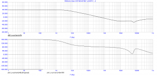
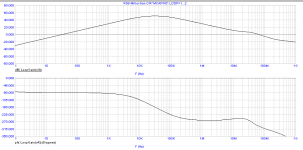
Regarding the first schematic, I have plotted the gain/phase response of the CMCL (which looks okay) respectively the Miller loop (with disabled global NFB loop).
It's the latter that predicts trouble, as the ULGF is way too high: 65MHz.
Notice that this is a rough estimation, as parasitics were ignored. A real amp might give quite different results and/or might even oscillate.
If you don't mind, I'm not gonna investigate this any further, because you changed the circuit every time and it deviates too much from the starting point as depicted in this post: http://www.diyaudio.com/forums/soli...ogy-construction-troubles-17.html#post2268194
Cheers,
E.
PS1: The plots show the loop gain, thus not the return value, which is - (minus) loop gain.
PS2: @Walter cs. "simulation [...] used to AC analyze the loop gain - that's the type of analysis where simulators are shining." Clearly NOT !
You are driving me nuts. I just analyzed (simmed) the schematic in post 2258, and in the meantime you pop up with another one in post 2264. Shooting at moving targets makes things not easier.
Regarding the first schematic, I have plotted the gain/phase response of the CMCL (which looks okay) respectively the Miller loop (with disabled global NFB loop).
It's the latter that predicts trouble, as the ULGF is way too high: 65MHz.
Notice that this is a rough estimation, as parasitics were ignored. A real amp might give quite different results and/or might even oscillate.
If you don't mind, I'm not gonna investigate this any further, because you changed the circuit every time and it deviates too much from the starting point as depicted in this post: http://www.diyaudio.com/forums/soli...ogy-construction-troubles-17.html#post2268194
Cheers,
E.
PS1: The plots show the loop gain, thus not the return value, which is - (minus) loop gain.
PS2: @Walter cs. "simulation [...] used to AC analyze the loop gain - that's the type of analysis where simulators are shining." Clearly NOT !
Attachments
Hi Edmond,
I understand the trouble of me changing the circuit, but the one you analysed (2258) is the one on the test bench. So that's perfect. This PCB is foreseen for additional components. So in fact the PCB corresponds to the schematic in 2264 but is only equiped with the components of 2258.
The TMC part is just replaced with one 1 cap on each side 33pF for a simple dom. pole compensation (for now).
Some other part may differ like C12/C13 and C15/C16 but the real ones plugged in are according to 2258 (and not 2264).
About the deviation from the starting point, indeed it looks more to the circuit you posted just before the version you linked to.
Thanks for the info, I know now I should rather look into the Miller loop instead of the CMCL loop even if the affected nodes are around the CMCL and ML... But I guess this is normal...
I wll post my findngs
Cheers
Olivier
Hi Envisionaudio,
Changing my probe from a 1/1 ratio to a 10/1 ratio removed the oscilation around R28 completely. It is expected to reduce 10x on the trace (assuming equal scale) but it went down to nill. Even raising the scale 10 to 1 (should be same amplitude as with 1to1 probe) showed no oscillation.
However Edmonds findings about the Millerloop ULGF to 65MHz worries me.
Only I don't know how to simulate it...
Edmond, could you explain how to measure the millerloop AC analyses (& cmcl loop - will be the same logic i assume)
Cheers
Hi Everyone,
I hope the situation at this moment is stable and not just a combination of hazards that come out well today but not tomorrow.
At the moment the amplifier behaves very well.
I even lowered the miller caps from 47pF to 22pF to see if any shakiness starts to sneak in.
The amplifier has a BW (-3dB) of 1Hz up to 1MHz.
It's slew rate is around 200V/us.
It's phase lag at 1MHz from the input signal is 36°
Checked scopetrace for peaking (sinuswave) from 1KHz to 5MHz (result = no peaking)
No overshoot on square wave (checked = OK)
Loads were never connected
Should still check if other nodes are oscillation free going through the bandwidth.
One strange thing I noticed however. As for sinewave the upper -3dB is @ 1MHz it seems 1,5MHz if square waves are used ? Why is that ?
Put simply : the output at say 1,2MHz is 20 to 30% higher if SQUAREWAVE compared to SINEWAVE ... any clues? This is not the case at lower frequencies of say 10KHz...
I'll continue trsting
Cheers
Olivier
Hi Envisionaudio,
Changing my probe from a 1/1 ratio to a 10/1 ratio removed the oscilation around R28 completely. It is expected to reduce 10x on the trace (assuming equal scale) but it went down to nill. Even raising the scale 10 to 1 (should be same amplitude as with 1to1 probe) showed no oscillation.
Great!
However Edmond's findings about the Miller loop ULGF to 65MHz worries me.
Only I don't know how to simulate it...
Edmond, could you explain how to measure the millerloop AC analyses (& cmcl loop - will be the same logic i assume)
Cheers
Yes I can, but first I need to know what version of MC do you have?
Cheers,
E.
Other than wiring/ground loops, PCB layout issues and RFI ingress, here are my bets (in the top-down likelihood order). Almost always very high frequency instabilities (5MHz and up) are due to local oscillations and not necessary related to the global feedback loop.
1. Local oscillations in the VAS cascode. At a minimum, you should add a small resistor in series to the Q21/Q24 collectors, 10-47ohm would do.
2. Miller local loop instability. The VAS transimpedance gain is huge (although C12/R25 and C13/R52 are trying to lower the HF gain), therefore the Miller loop (CM1/CM2) may require some frequency compensation. Add 47p in series with 47-100ohm from the Q22/Q23 collectors to the ground. Such a lead-lag compensation network usually helps.
3. The CMCL control loop seems to be compensated, not sure if C15/R33 and C16/R34 are good enough. If you determined the CMCL loop unity loop gain frequency and the phase margin, please post the method and the results.
4. Lack of decouplings, 10ohm/47nF for the entire board is definitely not enough. You should add local decouplings for each stage (input, VAS, output).
Hi Waly,
This is an excellent set of suggestions.
As an aside, I often assert that some of the sound quality differences among amplifiers are a result of them misbehaving differently - in ways that often do not show up in ordinary bench testing. HF parasitic oscillations, some of which cannot be easily seen at the output of an amplifier, are a good example. There may be a good number of smart amplifier designers out there making commercial audio amplifiers that are nevertheless having occasional (sometimes chirping) parasitic oscillations that they are unaware of. These can sometimes be very subtle. I have seen amplifiers on my own bench that were showing perhaps 0.01% of unexplained THD (perhaps should have been 0.003 or lower) only to find that there was some HF parasitic oscillation going on.
Cheers,
Bob
Hi Envisionaudio,
Changing my probe from a 1/1 ratio to a 10/1 ratio removed the oscilation around R28 completely.
Cheers
Put simply : the output at say 1,2MHz is 20 to 30% higher if SQUAREWAVE compared to SINEWAVE ... any clues?
1:10 probes have a much lower equivalent C compared to 1:1 probes. Both symptoms you decribed (sensitivity to capacitive loads and frequency response overshooting when driven towards slew rate limitations) are good signs of marginal stability.
I understand your displeasure to hack an expensive four layer PCB but, unless you decide to compensate the Miller loop, you can't expect anything but further trouble, in particular for reactive loads. The simplest way to compensate the Miller loop is to add lead-lag networks, as I mentioned in post #2262.
Hi Waly,
This is an excellent set of suggestions.
As an aside, I often assert that some of the sound quality differences among amplifiers are a result of them misbehaving differently - in ways that often do not show up in ordinary bench testing. HF parasitic oscillations, some of which cannot be easily seen at the output of an amplifier, are a good example. There may be a good number of smart amplifier designers out there making commercial audio amplifiers that are nevertheless having occasional (sometimes chirping) parasitic oscillations that they are unaware of. These can sometimes be very subtle. I have seen amplifiers on my own bench that were showing perhaps 0.01% of unexplained THD (perhaps should have been 0.003 or lower) only to find that there was some HF parasitic oscillation going on.
Cheers,
Bob
Hi Bob,
What is your method for finding parasitic oscillation that doesn't show up at the output?
Cheers,
David.
Marginal Stability
Hi Edmond,
I use MC907 for simulation.
Hi Waly,
I am indeed afraid stability isn't top notch and agree with your recommandations. However lowering the miller caps from 47p to 22p didn't give any sign of shakiness compared to the 47p caps. According to Bob this is one of the tests one should consider to check for marginality.
Maybe I wasn't clear in my other posting but on the output there never was oscillation not even with the 1 to 1 probe. It was only near the CMCL loop at first. I had 6 to 7 MHz oscillations on the RED lines on the posted schematic and around 30MHz around the BLUE line (which is around R28).
The RED issue got away while rearanging grounding. So I guess this came because of a ground loop. The second one, the BLUE one, kept there ... It only dissapears with my 10 to 1 probe. The 1 to 1 probe always shows the same result independant of the miller caps (47p or 22p). So I guess after all, maybe the circuit isn't limitly stable. However I would like to be more certain of it. Therefore I asked Edmond for help about loop stability simulation. The 10 to 1 probe is realy slow going from one node to another with opposing DC voltages (scope on AC scale). The trace seems like to come down from heaven in a slow elevator (or vice versa).
Not sure if capacitive load on the output will bring trouble. I will test that too very soon.
Could you just explain me better why the output seems higher in amplitude for squarewave than for sinewave? Anyway the squarewave looks like a sinewave at that frequency (1MHz). Maybe another info : while at Squarewaving at 1MHz the input signal (or output of the generator) seems to have overshoot and some amount of ringing. This is not the case on the output of the amp (it couldn't ring because it's no square at all anymore as i said it's sine or something like it anyway).
Problem is I cannot THD the amp to see if the seemingly very nice looking SINE on the scope is realy good as it looks.
Any hint for a THD analyser (BUY) ?
About the 4L PCB no problem to chop it up but I first try less invasive things. However it will come to that even if it were just for checking. The OPS is dummy anyway (just 1 EF BJT stage which is stil low power BJT)
Money is no issue, I grow my money on a tree here in the garden. Just kidding
Cheers
Olivier
Hi Oliver,
If you low pass filter the output of a square wave generator with a filter having a corner frequency (F3) at or near the fundamental of the square wave the output will look like a sine wave. The low pass filter removes the harmonics which make up the square wave and so you're left with more of a sinusoidal wave form.
Since the overshoot and ringing of the square wave from your generator represent higher order harmonics of the fundamental, these will be attenuated by any low pass filter effect from your amplifier's compensation.
1MHz is quite a high frequency to put into a power amplifier. My guess is that your running the frequency into the 6dB/octave slope established by the amplifier's compensation.
Even if you run a square wave within the bandwidth of an amplifier, as you approach the slope in frequency some of the harmonics of the square waveform will be attenuated.
David.
Hi Edmond,
I use MC907 for simulation.
Hi Olivier,
Okay. That means we can't use the more sophisticated Tian gain probe (for the first time possible in MC10). So I will revert to a simpler (and slightly less accurate) method to assess to loop gain and phase.
...........
Not sure if capacitive load on the output will bring trouble. I will test that too very soon.
At the moment, I wouldn't do that. There are better ways to tame the VAS.
Together with the schematics for assessing the loop properties, I will show you (soon) how to reduce the ULGF of the Miller to an acceptable value.
............
Cheers
Olivier
But first, it's time to stroll on to the local pub.

E.
Hi Olivier
Maybe I'm missing something, but when I read your posts it seems like you don't use a proper OPS and don't use a LOAD.
What is the point in designing an amplifier without an output stage and no load?
I suggest that you include an output stage and a real load (that's where the problems start) before you talk about stability. my 2c
Cheers
Stein
Hi Stinius,
The reason not to do a real OPS right now is to prevent 10$ fets from getting fried all the time. The reason however there is one (dummy for the moment) is to have at least a form of correct load for my IPS through the feedback network. Returning a high impedance VAS back to the IPS seems a no no.
Hi Edmond,
Have a good beer. I am eager to learn more about assessing the loop properties. I didn't do any testing today so nor did I capacitively load the OPS. It is indeed better to analyse ad fundum the VAS properties instead of shooting at it with capacitive loading and other taunteries to see if it survives.
Hi Davada,
OK I follow your explanation. However, it still does not explain why the 1MHz squarewave is bigger in amplitude as the 1MHz sinewave looking on the output of the amplifier (for clarity : I just switch the function generator from sine to square).
Anything to do with rms vs peak? I guess not.
Indeed the F3 (-3dB) point of the amp is high (1MHz) but this is also because there is no input low pas filter on the amps ingress. Later we can fix the F3 at say 250KHz or whatever. But lets try to figure out what's in the box before wrapping it in present paper
Cheers !
1:10 probes have a much lower equivalent C compared to 1:1 probes. Both symptoms you decribed (sensitivity to capacitive loads and frequency response overshooting when driven towards slew rate limitations) are good signs of marginal stability.
I understand your displeasure to hack an expensive four layer PCB but, unless you decide to compensate the Miller loop, you can't expect anything but further trouble, in particular for reactive loads. The simplest way to compensate the Miller loop is to add lead-lag networks, as I mentioned in post #2262.
I also use another trick with probes. Sometimes we really want to use a 1:1 either with a scope for sensitivity, or with an AC voltmeter not designed for 10:1 probes, or with a DVM to measure voltages. For this purpose, I have some of my own probes with a series resistor right in the tip. The value is 100 ohms or 1k ohm. Such a resistor does a good job of isolating the capacitance of the probe wiring from the circuit.
This technique can be applied to shielded probes or ordinary unshielded meter probes.
Of course, one has to realize that some HF response is given up with this approach. For example, the 1k resistor with total probe & instrument capacitance of 100 pF has a corner at 1.6 MHz. Thus, this approach is not good at seeing parasitic oscillations. Rather, it is good at seeing things without causing parasitic oscillations.
Cheers,
Bob
- Home
- Amplifiers
- Solid State
- Bob Cordell's Power amplifier book