G.Kleinschmidt said:
So why does this gate signal have to come from an oscillator?
Why not just a resistor from a fixed potential of, say, +10V above A2?
Draw a proposed schematic with all the details (delay, etc...) and you'll probably understand yourself.
The new gate pulse has to come while the A1-A2 voltage is not zero. That's why the oscillator frequency can't be (say) 1MHz, it is to close to the zero crossing. It also can't be 1KHz, the triac would have time to turn off.
G.Kleinschmidt said:
So why does this gate signal have to come from an oscillator?
Why not just a resistor from a fixed potential of, say, +10V above A2?
Cheers,
Glen
That'll work. If you take a sensitive gate triac, the trigger current/power can be insignificant.
You can also use a 90 degr phase shift RC so that the voltage across the R is max when the mains go through zero and vice versa.
Jan Didden
janneman said:
That'll work. If you take a sensitive gate triac, the trigger current/power can be insignificant.
You can also use a 90 degr phase shift RC so that the voltage across the R is max when the mains go through zero and vice versa.
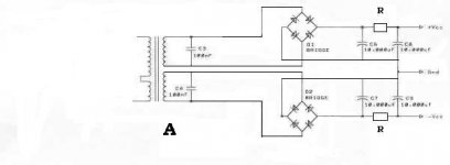
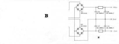
Something like in the attachment (a copy paste from some documentation I have around, this is for inrush current protection of a device fed by already rectified mains) would probably work fine. Could somebody make it simpler and still foolproof?
BTW, this is a link to Eva's original post with this circuit. It doesn't use a sensitive device, though.
http://www.diyaudio.com/forums/showthread.php?postid=1047047#post1047047
Attachments
It get more and more complicated. I still think that as Glen wants to use a PIC, there's an elegant solution for this. Put the mains phase through a series R and a 4.7V zener to get a 50 (60) Hz square wave at the zero xings at one input. Then delay after every polarity change/zero xing, and after the delay, send out a single firing pulse to the triac.
Start with a delay to fire just before the next zero xing so the conduction is only a very short time (the triac switches off again at the zero xing). Then progressively shorten the delay so firing occurs more and more earlier, until firing occurs right at the zero xing for full conduction. In this way you can nicely ramp up the supply, avoiding in-rush currents without any additional power parts or relays.
Jan Didden
On a similar subject, has anybody figured out how the Bryston soft start circuit (schematic PDF here) works? This seems to use a technique similar to what Jan just described above, which avoids the power resistor. It uses the TDA1085C chip. I have tried going through the datasheet of this chip, but it's quite possibly the worst datasheet I have ever read.
I really like the idea of eliminating that power resistor.
I really like the idea of eliminating that power resistor.
janneman said:
That'll work. If you take a sensitive gate triac, the trigger current/power can be insignificant.
You can also use a 90 degr phase shift RC so that the voltage across the R is max when the mains go through zero and vice versa.
Jan Didden
Thanks. This is what I was getting at in my first post on the topic. I can see the logic in using an oscillator to keep the average trigger current low, but not with a <5mA Igt TRIAC.
Cheers,
Glen
andy_c asked
has anybody figured out how the Bryston soft start circuit (schematic PDF here) works?
The TDA1085 is designed as a closed-loop motor speed controller. But in this case, the closed loop motor control is disabled - there is no tacho or analogue speed sense used. Instead the motor set speed is determined by an RC network (C6 - 100uF plus R17/18/20) so the set speed will 'slowly' ramp from zero to full speed after turn-on.
janneman said:It get more and more complicated. I still think that as Glen wants to use a PIC, there's an elegant solution for this. Put the mains phase through a series R and a 4.7V zener to get a 50 (60) Hz square wave at the zero xings at one input. Then delay after every polarity change/zero xing, and after the delay, send out a single firing pulse to the triac.
Start with a delay to fire just before the next zero xing so the conduction is only a very short time (the triac switches off again at the zero xing). Then progressively shorten the delay so firing occurs more and more earlier, until firing occurs right at the zero xing for full conduction. In this way you can nicely ramp up the supply, avoiding in-rush currents without any additional power parts or relays.
Jan Didden
What noises are my toroids likely to make with such a set up?
I'd prefer a couple of big resistors bolted to my series pass regulator heatsinks to an unglamorous power up fart.
I've already got the 50Hz being fed into the PIC as a mains voltage sense for other purposes, so all the phase control would require is some trivial additional code.
Cheers,
Glen
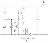
syn08 said:
Draw a proposed schematic with all the details (delay, etc...) and you'll probably understand yourself.
Attachments
G.Kleinschmidt said:
Thanks Glen, now I understand... Though, I would rather not do it this way. Reason is that the whole thing sits in the hands of C2 (electrolytic). As soon as C2 will dry out, the thing will crash and burn. In the original schematic, C2 has only to provide the gate current only during the pulses, that's why C2 can be smaller in value.
It seems like you don't have a good triac model; here's one:
.SUBCKT MAC08MT1 MT2 gate MT1 PARAMS:
+ Vdrm=600v Idrm=10u
+ Ih=5ma dVdt=10e6
+ Igt=10ma Vgt=2.0v
+ Vtm=1.9v Itm=1.1
+ Ton=1.5u
* Where:
* Vdrm => Forward breakover voltage
* Idrm => Peak blocking current
* Ih => Holding current [MT2(+)]
* dVdt => Critical value for dV/dt triggering
* Igt => Gate trigger current [MT2(+),G(-)]
* Vgt => Gate trigger voltage [MT2(+),G(-)]
* Vtm => On-state voltage
* Itm => On-state current
* Ton => Turn-on time
* Main conduction path
Striac MT2 MT20 cntrol 0 Vswitch ; controlled switch
Dak1 MT20 MT22 Dak OFF ; triac is initially off
VIak MT22 MT1 ; current sensor
Striacr MT2 MT23 cntrolr 0 Vswitch ; controlled switch
Dka1 MT21 MT23 Dak OFF ; triac is initially off
VIka MT1 MT21 ; reverse current sense
* dVdt Turn-on
Emon dvdt0 0 TABLE {ABS(V(MT2,MT1))} (0 0) (2000 2000)
CdVdt dvdt0 dvdt1 100pfd ; displacement current
Rdlay dvdt1 dvdt2 1k
VdVdt dvdt2 MT1 DC 0.0
EdVdt condvdt 0 TABLE {i(vdVdt)-100p*dVdt} (0 0 ) (.1m 10)
RdVdt condvdt 0 1meg
* Gate
Rseries gate gate1 {(Vgt-0.65)/Igt}
Rshunt gate1 gate2 {0.65/Igt}
Dgkf gate1 gate2 Dgk
Dgkr gate2 gate1 Dgk
VIgf gate2 MT1 DC 0.0 ; current sensor
* Gate Turn-on
Egate congate 0 TABLE {(ABS(i(VIgf))-0.95*Igt)} (0 0) (1m 10)
Rgate congate 0 1meg
* Holding current, holding voltage (Quadrant I)
Emain1 main1 0 TABLE {i(VIak)-Ih+5e-3*i(VIgf)/Igt} (0 0) (.1m 1)
Rmain1 main1 0 1meg
Emain2 main2 0 TABLE {v(MT2,MT1)-(Ih*Vtm/Itm)} (0 0) (.1m 1)
Rmain2 main2 0 1meg
Emain3 cnhold 0 TABLE {v(main1,0)*v(main2,0)} (0 0 (1 10)
Rmain3 cnhold 0 1meg
* Holding current, holding voltage (Quadrant III)
Emain1r main1r 0 TABLE {i(VIka)-Ih-5e-3*i(VIgf)/Igt} (0 0) (.1m 1)
Rmain1r main1r 0 1meg
Emain2r main2r 0 TABLE {v(MT1,MT2)-(Ih*Vtm/Itm)} (0 0) (.1m 1)
Rmain2r main2r 0 1meg
Emain3r cnholdr 0 TABLE {v(main1r,0)*v(main2r,0)} (0 0 (1 10)
Rmain3r cnholdr 0 1meg
* Main
Emain4 main4 0 table {(1.0-ABS(i(VIgf))/Igt)} (0 0) (1 1)
Rmain4 main4 0 1meg
Emain5 cnmain 0 table {v(mt2,mt1)-1.05*Vdrm*v(main4)} (0 0) (1 10)
Rmain5 cnmain 0 1meg
Emain5r cnmainr 0 table {v(mt1,mt2)-1.05*Vdrm*v(main4)} (0 0) (1 10)
Rmain5r cnmainr 0 1meg
* Turn-on/Turn-off control (Quadrant I )
Eonoff contot 0 TABLE
+ {v(cnmain)+v(congate)+v(cnhold)+v(condvdt)} (0 0) (10 10)
* Turn-on/Turn-off delays (Quadrant I)
Rton contot dlay1 825
Dton dlay1 cntrol Delay
Rtoff contot dlay2 {2.9E-3/Ton}
Dtoff cntrol dlay2 Delay
Cton cntrol 0 {Ton/454}
* Turn-on/Turn-off control (Quadrant III)
Eonoffr contotr 0 TABLE
+ {v(cnmainr)+v(congate)+v(cnholdr)+v(condvdt)} (0 0) (10 10)
* Turn-on/Turn-off delays (Quadrant III)
Rtonr contotr dlayr1 825
Dtonr dlayr1 cntrolr Delay
Rtoffr contotr dlayr2 {2.9E-3/Ton}
Dtoffr cntrolr dlayr2 Delay
Ctonr cntrolr 0 {Ton/454}
* Controlled switch model
.MODEL Vswitch vswitch
+ (Ron = {(Vtm-0.7)/Itm}, Roff = {1.75E-3*Vdrm/Idrm},
+ Von = 5.0, Voff = 1.5)
* Diodes
.MODEL Dgk D (Is=1E-16 Cjo=50pf Rs=5)
.MODEL Delay D (Is=1E-12 Cjo=5pf Rs=0.01)
.MODEL Dak D (Is=4E-11 Cjo=5pf)
* Allow the gate to float if required
Rfloat gate MT1 1e10
.ends
VivaVee said:The TDA1085 is designed as a closed-loop motor speed controller. But in this case, the closed loop motor control is disabled - there is no tacho or analogue speed sense used. Instead the motor set speed is determined by an RC network (C6 - 100uF plus R17/18/20) so the set speed will 'slowly' ramp from zero to full speed after turn-on.
Thanks very much! Maybe a good way to test it on the bench would be to have a variable DC into the speed control input using a pot. Then I assume by varying this voltage, the duty cycle of the AC will vary.
Andy,
You may find this circuit friendlier to understand and use:
http://focus.ti.com/lit/ds/symlink/uc3637.pdf
Free samples are, of course, available I was looking myself into this one, but I had no time to play with...
You may find this circuit friendlier to understand and use:
http://focus.ti.com/lit/ds/symlink/uc3637.pdf
Free samples are, of course, available
I was looking myself into this one, but I had no time to play with...syn08 said:
You may find this circuit friendlier to understand and use:
http://focus.ti.com/lit/ds/symlink/uc3637.pdf
Free samples are, of course, available
Looks promising!
andy_c wrote
Maybe a good way to test it on the bench would be to have a variable DC into the speed control input using a pot. Then I assume by varying this voltage, the duty cycle of the AC will vary.
Yes. The chip is specifically designed for triac phase control - unlike the UC3637.
I'm not sure what you see as a disaster in that datasheet. It was clearly designed to be pretty application specific so if you do not have that application in mind then it may get a bit confusing. If you think that is a disaster - well, you ain't seen nothing!
It appears to have been written in a language other than English and translated by someone that doesn't appear to know engineering. Here's some examples:
"This half wave current is used to feed a smothering capacitor..."
"All along the main line cycle, the Pin 10 dynamic range must not be exceeded unless loss of regulation."
Granted the designer or translator may not have good English skills, but this sort of stuff should be proofread before being published. Also, the schematic in Figure 8 looks like some sort of practical joke.
It does look like a good part for the application though.
syn08 said:
Thanks Glen, now I understand... Though, I would rather not do it this way. Reason is that the whole thing sits in the hands of C2 (electrolytic). As soon as C2 will dry out, the thing will crash and burn. In the original schematic, C2 has only to provide the gate current only during the pulses, that's why C2 can be smaller in value.
It seems like you don't have a good triac model; here's one:
.SUBCKT MAC08MT1 MT2 gate MT1 PARAMS:
+ Vdrm=600v Idrm=10u
+ Ih=5ma dVdt=10e6
+ Igt=10ma Vgt=2.0v
+ Vtm=1.9v Itm=1.1
+ Ton=1.5u
* Where:
* Vdrm => Forward breakover voltage
* Idrm => Peak blocking current
* Ih => Holding current [MT2(+)]
* dVdt => Critical value for dV/dt triggering
* Igt => Gate trigger current [MT2(+),G(-)]
* Vgt => Gate trigger voltage [MT2(+),G(-)]
* Vtm => On-state voltage
* Itm => On-state current
* Ton => Turn-on time
* Main conduction path
Striac MT2 MT20 cntrol 0 Vswitch ; controlled switch
Dak1 MT20 MT22 Dak OFF ; triac is initially off
VIak MT22 MT1 ; current sensor
Striacr MT2 MT23 cntrolr 0 Vswitch ; controlled switch
Dka1 MT21 MT23 Dak OFF ; triac is initially off
VIka MT1 MT21 ; reverse current sense
* dVdt Turn-on
Emon dvdt0 0 TABLE {ABS(V(MT2,MT1))} (0 0) (2000 2000)
CdVdt dvdt0 dvdt1 100pfd ; displacement current
Rdlay dvdt1 dvdt2 1k
VdVdt dvdt2 MT1 DC 0.0
EdVdt condvdt 0 TABLE {i(vdVdt)-100p*dVdt} (0 0 ) (.1m 10)
RdVdt condvdt 0 1meg
* Gate
Rseries gate gate1 {(Vgt-0.65)/Igt}
Rshunt gate1 gate2 {0.65/Igt}
Dgkf gate1 gate2 Dgk
Dgkr gate2 gate1 Dgk
VIgf gate2 MT1 DC 0.0 ; current sensor
* Gate Turn-on
Egate congate 0 TABLE {(ABS(i(VIgf))-0.95*Igt)} (0 0) (1m 10)
Rgate congate 0 1meg
* Holding current, holding voltage (Quadrant I)
Emain1 main1 0 TABLE {i(VIak)-Ih+5e-3*i(VIgf)/Igt} (0 0) (.1m 1)
Rmain1 main1 0 1meg
Emain2 main2 0 TABLE {v(MT2,MT1)-(Ih*Vtm/Itm)} (0 0) (.1m 1)
Rmain2 main2 0 1meg
Emain3 cnhold 0 TABLE {v(main1,0)*v(main2,0)} (0 0 (1 10)
Rmain3 cnhold 0 1meg
* Holding current, holding voltage (Quadrant III)
Emain1r main1r 0 TABLE {i(VIka)-Ih-5e-3*i(VIgf)/Igt} (0 0) (.1m 1)
Rmain1r main1r 0 1meg
Emain2r main2r 0 TABLE {v(MT1,MT2)-(Ih*Vtm/Itm)} (0 0) (.1m 1)
Rmain2r main2r 0 1meg
Emain3r cnholdr 0 TABLE {v(main1r,0)*v(main2r,0)} (0 0 (1 10)
Rmain3r cnholdr 0 1meg
* Main
Emain4 main4 0 table {(1.0-ABS(i(VIgf))/Igt)} (0 0) (1 1)
Rmain4 main4 0 1meg
Emain5 cnmain 0 table {v(mt2,mt1)-1.05*Vdrm*v(main4)} (0 0) (1 10)
Rmain5 cnmain 0 1meg
Emain5r cnmainr 0 table {v(mt1,mt2)-1.05*Vdrm*v(main4)} (0 0) (1 10)
Rmain5r cnmainr 0 1meg
* Turn-on/Turn-off control (Quadrant I )
Eonoff contot 0 TABLE
+ {v(cnmain)+v(congate)+v(cnhold)+v(condvdt)} (0 0) (10 10)
* Turn-on/Turn-off delays (Quadrant I)
Rton contot dlay1 825
Dton dlay1 cntrol Delay
Rtoff contot dlay2 {2.9E-3/Ton}
Dtoff cntrol dlay2 Delay
Cton cntrol 0 {Ton/454}
* Turn-on/Turn-off control (Quadrant III)
Eonoffr contotr 0 TABLE
+ {v(cnmainr)+v(congate)+v(cnholdr)+v(condvdt)} (0 0) (10 10)
* Turn-on/Turn-off delays (Quadrant III)
Rtonr contotr dlayr1 825
Dtonr dlayr1 cntrolr Delay
Rtoffr contotr dlayr2 {2.9E-3/Ton}
Dtoffr cntrolr dlayr2 Delay
Ctonr cntrolr 0 {Ton/454}
* Controlled switch model
.MODEL Vswitch vswitch
+ (Ron = {(Vtm-0.7)/Itm}, Roff = {1.75E-3*Vdrm/Idrm},
+ Von = 5.0, Voff = 1.5)
* Diodes
.MODEL Dgk D (Is=1E-16 Cjo=50pf Rs=5)
.MODEL Delay D (Is=1E-12 Cjo=5pf Rs=0.01)
.MODEL Dak D (Is=4E-11 Cjo=5pf)
* Allow the gate to float if required
Rfloat gate MT1 1e10
.ends
Weeelll in my amplifier I’m using a small PCB mount transformer to provide the floating supply for the TRAIC gate trigger circuitry.
I do not think that C2 failure in this type of circuit is any more of an issue than failure of the series capacitor providing the supply current directly from the mains.
In such a circuit I’d be sure to use a class of capacitor designed to fail open circuit.
Anyway, a zener diode (as in your circuit) across C2 will prevent a crash and burn in the case of C2 drying out. In any case the circuit would require, at bare minimum, a resistor in parallel with C2 anyway, to discharge it at power down, ready for the next power up.
An inability to cope with brief power interruptions is a fault I see with most soft start circuits around here. Accidentally toggle the power switch or bump a power cord, the plug of which is only plugged half way into the wall outlet and bbbzzzztttttt…….
This is so in some phase control circuits also, which depend on a slow RC time constant. If the phase control circuit doesn’t fully reset during a brief power interruption, the TRIAC will likely turn back on at the worst possible moment and smoke if it wasn’t selected for a sufficiently high Itsm.
Many step-down transformers for low voltage home lighting (unless specifically designed for low in-rush current) are not recommended for use with simple TRIAC phase control light dimmers for this reason.
If you circuit does rely on slow RC time constant, a small relay with the coil energized by the AC mains after the power switch can be a simple solution – the normally closed contacts are connected across the capacitor. This way the capacitor is discharged immediately when the power is switched off or accidentally interrupted.
In my amplifier (which has a 240VAC/10A inlet for each channel due to the power requirement) instead of a power switch I am using a pair of multiple pole/contact relays to switch the AC mains prior to the PIC sequenced soft start circuitry.
The relays have 240VAC coils and are connected in parallel. They are connected to the AC mains via two series connected momentary push buttons, one a normally closed type and the other a normally open type. The normally open one is connected in parallel with a normally open pair or relay contacts and acts as the power ON button and the normally closed push button is the power OFF.
This is how small plant machinery is wired. The power ON/OFF buttons are only required to pass the relay coil current and the relay(s) drop out when power is interrupted, preventing the machinery from restarting.
Applied to the amplifier circuit, prior to the soft-start (I will either use TRIAC phase control or a pair of TRIACs in series/parallel with the in-rush limiting resistor so there is zero initial current to the 4kVA of toroidal primary windings), the relays only switch a small current (the supply transformers for the auxiliary control/sequencing circuitry) so contact wear isn’t an issue.
The AC mains switching relays also one level of redundancy in that a TRIAC breakdown or similar failure will not cause the amplifier power circuitry to draw current from the mains.
Cheers,
Glen
- Status
- This old topic is closed. If you want to reopen this topic, contact a moderator using the "Report Post" button.
- Home
- Amplifiers
- Solid State
- Bob Cordell Interview: Power Supplies