I personally find a "cap multiplier" style filtered source follower with an approbriate power MOSFET way simpler and usually better than fixed voltage regulated supplies at these power/current levels. Low power losses, low output ripple, low DC-stability (which IMHO no one needs for an output stage).
And I would use separated secondaries, dual bridges and 1:1 copies of the circuit for each rail (both N-Channel), which implies that "GND" is formed at the outputs.
I did such a circuit with IRFP2907's, with a second MOSFET that was put in the return legs and was driven hard on normally but was configured to produce a foldback current limiting.
- Klaus
If you have a closer look at the schematic, this IS a more elaborate version of a capacitance multiplier (look at what C1 is doing!)
The only difference is that the output voltage is fixed and a greater voltage is dropped across the series pass devices. But this overcomes a major operating flaw of the capacitance multiplier - things go bad when the input voltage sags below the charge on the base (or gate) capacitor under high load current demands.
Also, power dissipation isn't an issue with my heatsinks and I've got 25 spare pairs of MJL21193/MJL21194 to use up")
MOSFET's were ruled out because they give no where near as low an output impedance as the big bipolar CFP (Think of Vgs variation with Id of a source follower, then take another look at the simulated voltage droop of my circuit with 100A (!) load current.
You can of course make a MOSFET CFP with a bipolar driver for a follower, but it still isn't as good due to the much lower transconductance of power MOSFETs (especially HEXFETs).
Also, I will be using dual secondaries and dual bridge rectifiers, but the + and - regulators with be complementary mirrors of eachother. Not sure what the benefits WRT grounding are by using indentical (single polarity) regualtors in series)?
Cheers,
Glen
The only difference is that the output voltage is fixed and a greater voltage is dropped across the series pass devices. But this overcomes a major operating flaw of the capacitance multiplier - things go bad when the input voltage sags below the charge on the base (or gate) capacitor under high load current demands.
Also, power dissipation isn't an issue with my heatsinks and I've got 25 spare pairs of MJL21193/MJL21194 to use up
MOSFET's were ruled out because they give no where near as low an output impedance as the big bipolar CFP (Think of Vgs variation with Id of a source follower, then take another look at the simulated voltage droop of my circuit with 100A (!) load current.
You can of course make a MOSFET CFP with a bipolar driver for a follower, but it still isn't as good due to the much lower transconductance of power MOSFETs (especially HEXFETs).
Also, I will be using dual secondaries and dual bridge rectifiers, but the + and - regulators with be complementary mirrors of eachother. Not sure what the benefits WRT grounding are by using indentical (single polarity) regualtors in series)?
Cheers,
Glen
G.Kleinschmidt said:Hmmm.... I just looked up the datasheet for the IRFP2907. Only ~0.9V Vgs variation for an Id variation of 10A to 100A.
Not bad. Don't know how'd one could easily get even half the 470W Pdiss rating out of a TO-247 package though!
Or Onsemi's NTY100N10. Play nice and they'll send you 10pcs for free. They ship from Singapore so you'll have them in a couple of days.
But don't tell me you really need 4000S of transconductance from 25 MJL21193/MJL21194 in parallel. SOA, yes.
syn08 said:But don't tell me you really need 4000S of transconductance from 25 MJL21193/MJL21194 in parallel. SOA, yes.
Well, it's 20 in parallel plus one driver (I'm just trying to make a start at using up a 25 pc tube of each part
)20 devices gives waaayyyyy more SOA than I require, I just need so many pairs becuse the load current spec is 100A and the beta of these transistors goes down the tube at Ic >5A.
Also, the more transconductance the better, as that gives a lower output impedance.
My output stage (complementary EF) has 20 pairs of On Semi RET devices in parallel (again to be able to deliver 100A peak without entering the dramatic beta and fT droop region at Ic>5A) and with that many devices Cob stars to stack up, putting some demands on the driver stage.
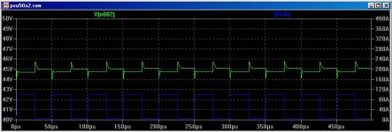
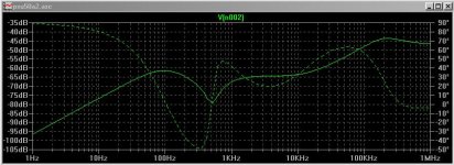
The super dooper OTT power supply will provide very clean rails for the output devices, with minimal rubbish to modulate the driver output via Cob (The rock stead rails will also work in conjunction with a VAS clamp to provide super clean clipping)
Below is the simmed ripple rejection (solid line)
Cheers,
Glen
Attachments
G.Kleinschmidt said:
Well, it's 20 in parallel plus one driver (I'm just trying to make a start at using up a 25 pc tube of each part
20 devices gives waaayyyyy more SOA than I require
Yes, as long as you don't have any overload conditions, not to mention an output short.
I still have to understand the reasoning beyond building such a power supply. I'm not debating the slight positive impact on the performance, but only if it's really worth the space, cost and power dissipation.
syn08 said:
Yes, as long as you don't have any overload conditions, not to mention an output short.
I still have to understand the reasoning beyond building such a power supply. I'm not debating the slight positive impact on the performance, but only if it's really worth the space, cost and power dissipation.
WRT short / Overload, I'm sure a "protection" circuit can be done to limit
current to only 120A or so.
T
Terry Demol said:
WRT short / Overload, I'm sure a "protection" circuit can be done to limit
current to only 120A or so.
T
Yes, that is exactly what I'm going to do, simply by sensing the voltage developed across one of the emitter current sharing resistors of the big CFP.
I just didn't bother adding this to the simulation.
G.Kleinschmidt said:
Yes, that is exactly what I'm going to do, simply by sensing the voltage developed across one of the emitter current sharing resistors of the big CFP.
I just didn't bother adding this to the simulation.
Yes, that's exactly when you may run into SOA problems. Under shortcircuit, 120A x whatever voltage you'll have left at that current (say 50V) makes 6kW, that is 300W/device. Look at the SOA curves in the datasheet (unfortunatley they don't publish the DC curve, but only at 1 sec) at 6A.
6kW, you are insane
You need a foldback protection.G.Kleinschmidt said:
Yes, that is exactly what I'm going to do, simply by sensing the voltage developed across one of the emitter current sharing resistors of the big CFP.
I just didn't bother adding this to the simulation.
I was joking of course - hence the " " around protection.
OK, so what is this thing going to drive, a paralleled line array
or something?
T
syn08 said:
Yes, that's exactly when you may run into SOA problems. Under shortcircuit, 120A x whatever voltage you'll have left at that current (say 50V) makes 6kW, that is 300W/device. Look at the SOA curves in the datasheet (unfortunatley they don't publish the DC curve, but only at 1 sec) at 6A.
6kW, you are insane
No! the over current protection system I intend to implement will simply crowbar and shut down the power supply completely and mute the audio input signal. It will stay that way until manually reset.
The series pass transistors in the psu will only ever drop approximately 15-20V while delivering the rated current, which gives a worst case peak dissipation of only 100W in each series pass device when delivering a peak load current of 100A.
The average current/dissipation is much less. When delivering a continuous full amplitude (40V peak) sinewave into the minumum specified continuous power load resistance of 1 ohm (for a peak load current of 40A) the average current drawn from each supply rail will equal 40A/pi = 12.7A.
With 20V dropped across the 20 series pass devices the average dissipation will only be a minescule 12.7W per device.
Also note that this dissipation is under continuous sinewave conditions, which no full amplitude music signal will ever replicate.
So, with music signals, the amp has enough SOA headroom to deliver peak currents of 100A into a low enough load impedance without breaking a sweat
Cheers,
Glen
Terry Demol said:OK, so what is this thing going to drive, a paralleled line array
or something?
Hmmm...... I haven't worked that out yet
AndrewT said:what about foldback limiting when the overload condition exists?
consider a peak hold indicator to show what is happening?
If an overload condition exists in an amp with this much load current headroom, then there is a fault somewhere and I'd prefer that the amplifier shuts itself down.
My original plan was to implement a standard I-limiter/clamp on the amplifier complementary bipolar output stage (OPS) set to ~100A, with the PSU crowbar set to trigger at a slightly lower current (say 80A), but after a preset time delay.
When operating, the current limiter on the OPS turns the output stage into a big , high input impedance current sink. This is important under short-circuit conditions because it prevents the regulated supply rails from being pulled to ground (as would happen if the current limiting/clamping was done in PSU), thus preventing the series pass transistors from being subjected to the SOA strain of the full unregulated rail voltage.
Now I think I will set the OPS limiter to clamp the output current at 120A, with the PSU crowbar operating if the load current exceeds 100A for 10mS.
This is within the temp-derated SOA limits for the MJL3281/MJL1302 BJT's I'm using in the output stage, assuming a short circuit at the output causing the output transistors to pass the full 120A of limited load current while dropping the full 45 volts of rail voltage.
The voltage drop across the series pass transistos in the PSU under these conditions is less than half that of the OPS, so they are ever safer.
For further protection, an intergrated (time constant of, say, 10 seconds) sample of the measured load current can also be used to trigger the PSU crowbar, but on a much lower current setting, as after being intergrated, it is the average value of load current that is being measured.
Cheers,
Glen
fuse?G.Kleinschmidt said:........For further protection, an integrated (time constant of, say, 10 seconds) sample of the measured load current can also be used to trigger the PSU crowbar, but on a much lower current setting, as after being integrated, it is the average value of load current that is being measured.
MikeW said:I have all the jumpers and diodes in. The tubes and sockets are on order.
Wrong thread man!
Just finished drawing the low current power supply circuit for the voltage amplifier part of a design of mine that requires +/-60V and +/-20V rails.
It's pretty self exlanatory. May give some that like to roll their own some ideas.
It's pretty self exlanatory. May give some that like to roll their own some ideas.
An externally hosted image should be here but it was not working when we last tested it.
- Status
- This old topic is closed. If you want to reopen this topic, contact a moderator using the "Report Post" button.
- Home
- Amplifiers
- Solid State
- Bob Cordell Interview: Power Supplies