Bob Cordell said:
Hi Rodolfo,
But look at the plot in Post 1513 above. Looks like it is doing a pretty good job on the 7th there.
.....
Hi Bob, you wondered what was Mr. Curl celebrating and this is my interpretation, not what I believe.
")
Rodolfo
PMA said:Would you also like to invistigate how real NFB (almost always frequency dependent) decreases high order harmonics of a conventional class B/AB output stage?
/for stepped output amplitude up to limitation/
Yes, this is a very good point. Although it is a departure from what Baxandall was trying to show, that would be a very good thing to do.
That real NFB often decreases with frequency in the audio band is a reality that is largely (but not solely) responsible for the increase in THD that we see in amplifiers as frequency is increased.
Then again, 30 dB of NFB at 20 kHz, the extent of the amount of NFB in Post 1513, is not uncommon in amplifiers. Of course, the phase angle of the NFB at that point will be closer to 90 degrees than to zero degrees, and that point bears review.
There is a related important point here. The HF distortion that is most likely the problem is the in-band IM created by the HF nonlinearity, as opposed to the harmonics themselves that lie well above the audible band. That is why I prefer the 19 + 20 kHz CCIF IM test for evaluating HF distortion. Those IM products, created in-band, are subjected to and reduced by the amount of NFB present at their in-band frequencies. For example, those odd-order IM products that lie on either side of the 19+20 kHz stimulous get the benefit of the amount of NFB present at around 20 kHz (like the 30 dB mentioned as typical above).
Cheers,
Bob
john curl said:This is where a computer could be very valuable. For example, I usually recommend 15mV-25mV drop across the resistor. However, maybe 35mV gives lowest 7th harmonic distortion at the transistion.... I don't know yet. ..... Who knows?
Yes, a computer seems to be valuable.
Attachments
I think we all agree, that in conventional designs feedback where it is MOST NEEDED from psychoacoustic point of view (trebles, transients, high order harmonics, class B discontinuity...) is LEAST efficient or there is smallest amount of it.
I don't like blanket statements, but "error correction rules"! indeed.
Adam
I don't like blanket statements, but "error correction rules"! indeed.
Adam
Looks good. Now, IF you can change the resistor Re up and down a little bit, we can see if we really have a null for 7th harmonic. However, please keep Iq at exactly the same place, if you can. Output must exceed class A boundry, but you are already doing that, so we might get an interesting result.
In truth, .1 ohm is a pretty low value for this Iq.
In truth, .1 ohm is a pretty low value for this Iq.
If I change the Re a little bit, I can find minimum for the 7th. But this only for just one amplitude of input signal. So I get 0.00048% of the 7th at 5V. This is definitely out of class A for 105 mA.
Yes, 105mA seems low. But it was the value where I got the lowest 7th. And also Re = about 0.1 seems to be good.
You have more output pairs then 1, don't you? So you will have N x 105mA.
Yes, 105mA seems low. But it was the value where I got the lowest 7th. And also Re = about 0.1 seems to be good.
You have more output pairs then 1, don't you? So you will have N x 105mA.
Attachments
>>What is wrong with this picture? Are they unaware of the capabilities of SPICE in this application? On the other hand, if they were aware of SPICE’s capabilities and thought them unsuitable, one would have expected them to mention that somewhere. Very curious.<<
Jerry is a friend of mine, I assure you he understands SPICE and I have confirmed the results are nearly the same. Solving a problem like this lends itself to hand analysis which would be his first approach. Having the equations in front of you can give some insight into relationships between component values. For instance two terms subtracting at just a certain bias level could jump right out at you.
Jerry is a friend of mine, I assure you he understands SPICE and I have confirmed the results are nearly the same. Solving a problem like this lends itself to hand analysis which would be his first approach. Having the equations in front of you can give some insight into relationships between component values. For instance two terms subtracting at just a certain bias level could jump right out at you.
scott wurcer said:>>What is wrong with this picture? Are they unaware of the capabilities of SPICE in this application? On the other hand, if they were aware of SPICE’s capabilities and thought them unsuitable, one would have expected them to mention that somewhere. Very curious.<<
Jerry is a friend of mine, I assure you he understands SPICE and I have confirmed the results are nearly the same. Solving a problem like this lends itself to hand analysis which would be his first approach. Having the equations in front of you can give some insight into relationships between component values. For instance two terms subtracting at just a certain bias level could jump right out at you.
Thanks for the explanation Scott. I guess I was just left scratching my head that there wasn't even a mention of SPICE in their paper. But to each his own, and you are certainly right that sometimes just looking at the math itself can be very revealing. I'm probably a lot lazier than Jerry as well
.Cheers,
Bob
NFB for Class-AB Output Stage
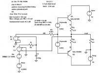
In the schematic below I have simulated a Class-AB output stage with and without negative feedback at an operating signal voltage that is around the worst case for crossover distortion, around 3 V peak into a 4 ohm load.
The stage uses the ThermalTrak RETs with Andy_c's models. It employs 0.22 ohm RE and is biased with about 23 mV across each RE. This is very slightly over-biased compared to optimum, but not by much. Idle current is 103 mA.
The circuit shown applies 34 dB of low-frequency NFB with an open-loop corner of 4 kHz for 20 dB of NFB at 20 kHz. Closed loop bandwidth is about 190 kHz.
In the subsequent posts I'll show the Fourier output spectrum for the circuit with and without negative feedback.
Cheers,
Bob
Attachments
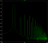
Here is the output spectrum of the Class-AB output stage with no negative feedback. The simulation schematic is shown in the previous post.
Note that the frequency scale goes out to 30 kHz and that the amplitude scale goes from +20 dB down to -200 dB.
Significant crossover distortion is in evidence out to very high frequencies, as expected.
Note that the 15th harmonic lies around -100 dB.
Bob
Note that the frequency scale goes out to 30 kHz and that the amplitude scale goes from +20 dB down to -200 dB.
Significant crossover distortion is in evidence out to very high frequencies, as expected.
Note that the 15th harmonic lies around -100 dB.
Bob
Attachments
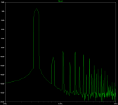
Here is the output spectrum with negative feedback.
Note that the 15th harmonic lies at about -120 dB. Negative feedback is doing an effective job of reducing even the high harmonics of the crossover distortion in accordance with expectations based on the amount of negative feedback available at the frequency of interest.
Cheers,
Bob
Note that the 15th harmonic lies at about -120 dB. Negative feedback is doing an effective job of reducing even the high harmonics of the crossover distortion in accordance with expectations based on the amount of negative feedback available at the frequency of interest.
Cheers,
Bob
Attachments
Bob Cordell said:Here is the output spectrum with negative feedback.
Note that the 15th harmonic lies at about -120 dB. Negative feedback is doing an effective job of reducing even the high harmonics of the crossover distortion in accordance with expectations based on the amount of negative feedback available at the frequency of interest.
Cheers,
Bob
Hi Bob,
thank you very much for your simulations. Yes, the NFB is doing the job, but the result is poor /I would rather say very poor/ (5th and 7th about -100dB). In real amplifiers, we can do it much better. For me, the output stage with minimal distortion is the solution. Then, after feedback application, we can get excellent results with almost no high harmonics.
Regards,
Pavel
Hi, PMA,
NP-PMA seems to have an interesting property compared to Hawksford EC. The opposite side seems won't turn off when 1 side is conducting (eg. negative side won't turn off when the positive side is conducting). Is this right?
For me, the output stage with minimal distortion is the solution
NP-PMA seems to have an interesting property compared to Hawksford EC. The opposite side seems won't turn off when 1 side is conducting (eg. negative side won't turn off when the positive side is conducting). Is this right?
- Home
- Amplifiers
- Solid State
- Bob Cordell Interview: Negative Feedback