Graham Maynard said:Hi Edmond,
Please show us how you established your findings in case there is something else here we need to study.
Cheers .......... Graham.
Hi Graham,
Look at this, I hope it helps.
Cheers,
Attachments
darkfenriz said:Edmond
How is stability on capactive loads affected?
Hi darkfenriz,
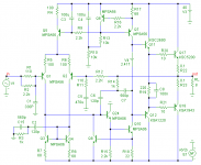
Almost nothing. With a relative large capacitor, directly tied to the output, that is, before the Zobel network, ringing becomes slightly more.
Notice: Although not shown in the diagram above, I simulated the effect of the twisted leads tot the output devices as well by means of series inductors of 50nF, mutually coupled with K=0.8.
btw, I'm eager to hear the comments on the role of C2, C15 and R3.
Cheers,
estuart said:
Hi darkfenriz,
Almost nothing. With a relative large capacitor, directly tied to the output, that is, before the Zobel network, ringing becomes slightly more.
Notice: Although not shown in the diagram above, I simulated the effect of the twisted leads tot the output devices as well by means of series inductors of 50nF, mutually coupled with K=0.8.
btw, I'm eager to hear the comments on the role of C2, C15 and R3.
Cheers,
thanks, that's interesting.
This passive network seems to symetrize impedance to ground of LTP collectors and probably improving PSRR, but I am not sure it works as intended.
andy_c said:
I think the intent of this circuit was to behave more or less like single pole comp, but including the output stage - while eliminating the instability problems of Cherry's proposal of simply hooking the Miller cap to the output. In that sense, I like the idea a lot. It's also good that it's stimulated some discussion and further thought. That keeps things lively and interesting. Cherry's response was simply one of denying any problem. But anyone with LTSpice with its loop gain probe can see that his proposed solution is potentially disastrous. In contrast, this is a constructive approach offering a solution and providing much food for further thought.
It appears to me that the high loop gain advantages of two-pole comp could be realized, along with stable inclusion of the output stage in the minor loop. I touched on a possible approach in an earlier post but haven't developed the idea fully yet. But I think this will take three capacitors. Such a solution could be compared unfavorably with a hypothetical three-pole comp in terms of the loop gain- but would that be fair? I think not.
In fact, I think the extra capacitor is a small price to pay for being able to include the output stage in the minor loop without incurring minor loop instability. In my view, this whole idea deserves lots of study and could lead to improved designs.
Andy, I agree completely. The concern about two-pole compensation was not that it did not provide good distortion reduction, it was with respect to its phase margin characteristics. This approach may not provide quite as much distortion reduction, but does not appear to compromise phase margin as much.
Hi Edmond,
You have lower input resistances at the diff-pair which I too prefer, and I see the capacitors at the mirror having much lower value than one of my own circuits (maybe tuned again) but there is otherwise little significant difference to the circuit I checked out.
As below.
Thus I feel the main difference between our approaches relate to examining output stage behaviour, and simulating with a load capable of introducing complex phase shift for a couple of cycles after sudden start (of which the first quadrant may be ignored for those who would wish to limit bandwidth considerations).
My test circuit uses an approximation for the DIY 'Ariel' loudspeaker (which has a higher crossover frequency than many simple designs) and I subtract an equal amplitude but fractionally phase shifted potential from the output voltmeter reading to view the output residual.
The steady sine THD figure was approx 0.002%, but the crossover spikes were not insignificant.
Cheers ........... Graham.
Attachments
Graham Maynard said:Hi Edmond,
You have lower input resistances at the diff-pair which I too prefer, and I see the capacitors at the mirror having much lower value than one of my own circuits (maybe tuned again) but there is otherwise little significant difference to the circuit I checked out.
As below.
Thus I feel the main difference between our approaches relate to examining output stage behaviour, and simulating with a load capable of introducing complex phase shift for a couple of cycles after sudden start (of which the first quadrant may be ignored for those who would wish to limit bandwidth considerations).
My test circuit uses an approximation for the DIY 'Ariel' loudspeaker (which has a higher crossover frequency than many simple designs) and I subtract an equal amplitude but fractionally phase shifted potential from the output voltmeter reading to view the output residual.
The steady sine THD figure was approx 0.002%, but the crossover spikes were not insignificant.
Cheers ........... Graham.
Hi Graham,
Thanks for your information. I certainly will have a careful look at it asap.
Cheers, Edmond.
The thread moved on whilst I added text and copied the test circuit
Edmond wrote >
btw, I'm eager to hear the comments on the role of C2, C15 and R3.
These components balance mirror action out at the rail wrt (signal) ground.
I use resistors on both halves of the mirror as illustrated in #498 above - resistors keep the local output feedback linear so that the effect of dynamic loudspeaker loads does not generate a reactive response within the global loop; ie. clean sound.
The 10pFs in this illustrative circuit are likely too low, and will need to be properly established.
Cheers .......... Graham.
andy_c said:
The sim I did with the minor feedback loop I showed was of my own amp design - not anything anyone posted here. Furthermore, the network I posted had no component values at all. So I don't think you can reach any conclusive results, because the info I posted was not sufficient to do so.
I'll put a loop gain probe in the inner loop, re-run the sim and post the results tomorrow.
Hi Andy,
Actually the component values are rather easy to sort out. For a start the series combination of all three capacitors in your modification should be equal to the equivalent single-pole Miller compensator if the forward-path's unity gain frequency is to remain unchanged.
For the same reason the component value in Edmond's arrangement should be identical to those selected for the equivalent DPC network.
Bob Cordell said:The concern about two-pole compensation was not that it did not provide good distortion reduction, it was with respect to its phase margin characteristics.
This is a non-problem.
estuart said:.....the intent of this circuit is to behave *exactly* like single pole comp, not more or less.
Only from the perspective of the input stage:
http://www.diyaudio.com/forums/showthread.php?postid=1160892#post1160892
estuart said:
I would suggest running sims first, before jumping to any conclusions. The same applies to you, Mike!
And remember, the reasonings of a human brain, including yours, are more prone to false conclusions then the the outcome of a sim.
I suppose, you do have a decent simulator and are able to use it in a proper way, do you?
So, go to work and stop your mindless shouting.
estuart said:
I don't think you are in the position to say things like that.
It's up to you to prove I'm wrong, that is, by means of hard evidence like a sim of a complete amp (the blameless for example), not by false reasoning.
As told before, my sims reveal an improvement of 15dB without any sign of instability. I have provided all the data you need, except spice models, but I suppose do have models, reliable ones of course.
Now, run that sim and don't behave like God or Einstein.
NB: In the event of a negative outcome, most unlikely, it still doesn't prove I'm wrong, rather you give further evidence of lack of expertise on your part.
This forum never ceases to amaze me in respect of some member's capacities to completely ignore or fail to read my posts, and then suggest I have failed to present proof.

Folks, please read these posts with great care, and run the loop gain sims for each concept therein:
http://www.diyaudio.com/forums/showthread.php?postid=1160809#post1160809
http://www.diyaudio.com/forums/showthread.php?postid=1160892#post1160892
Andy, below is conceptual circuit of your arrangement with the net loop gain experienced by the output stage available by merely plotting the following expression:
-1/(1-1/(2*(I(Vi1)@1*V(x)@2-V(x)@1*I(Vi1)@2)+V(x)@1+I(Vi1)@2))
Attachments
darkfenriz said:
This passive network seems to symetrize impedance to ground of LTP collectors and probably improving PSRR,
Hi,
You are quite right, particularly PSRR.
Regards,
I have been on the butt end of personal comments here before, and it makes you say to yourself "!!!.Why bother.!!!" especially when you know that you have made a correct statement(s), but others have interpreted differently either due to differences in technical approach or language comprehension, and then little arrows end up accompanying communications.
Edmond what you said about lowering the THD is correct, but
Mike was also correct about the dynamic response within the inner loop.
In the absence of anyone else showing simulations - I did - and they took me ages to set up, though even there I have shown only my own viewpoint; no one else's!
There is always more than one way for different people to look at the same thing, and different viewpoints are to be treasured as a sign of addressing different perceived needs rather than being proof of anyone's failed understanding or lack of education or experience.
I never did try the output stage linearising resistors in a real-world stand alone class-AB amplifier, but I use them in my class-A//AB circuit where they improve the loudspeaker damping response at higher AF.
Maybe they can improve standard class-AB amplifiers without needing to increase quiescent consumption and without needing more complex circuitry. They do need an input diff+mirr to function correctly though.
It is not about who is correct or not. Everyone's view has merit. It is simply about peer respect, even if you disagree. I was aiming at all parties showing lack of that respect.
As you all will agree, this has become a most splendid thread, lets not spoil it with ego boosting.
Now, can we go back on topic? My mailbox is open 24/7 for eventual comments, please refrain from posting them here.
/Hugo
As you all will agree, this has become a most splendid thread, lets not spoil it with ego boosting.
Now, can we go back on topic? My mailbox is open 24/7 for eventual comments, please refrain from posting them here.
/Hugo
andy_c said:
I think the intent of this circuit was to behave more or less like single pole comp, but including the output stage - while eliminating the instability problems of Cherry's proposal of simply hooking the Miller cap to the output. In that sense, I like the idea a lot. It's also good that it's stimulated some discussion and further thought. That keeps things lively and interesting. Cherry's response was simply one of denying any problem. But anyone with LTSpice with its loop gain probe can see that his proposed solution is potentially disastrous. In contrast, this is a constructive approach offering a solution and providing much food for further thought.
Reading this part of the post made me remember what Doug Self said about this approach (Cherry's scheme) in his power amp design handbook. I beleive he cited references to Bob Widlar that said the output stage has to be well controlled to 100Mhz. I think it was from an IC design handbook or something. And with what Bob Cordell has said about the ft off some vertical power mosfets being 300Mhz it might be possible. Would probably need really fast mosfet drivers too also.
Obviously we can forget any BJTs in this app.
I can get the references if needed.
Fanuc said:I beleive he cited references to Bob Widlar that said the output stage has to be well controlled to 100Mhz. I think it was from an IC design handbook or something.
I've seen this reference, but I can't remember what it was! Maybe an article on an IC power amp.
If you have LTSpice, you can use the loop gain probe to analyze the stability of the VAS loop by itself. In the global feedback network, put a huge inductor in series, say 1e20 Henries. Then put the loop gain probe inside the VAS loop. Now you're looking at the loop gain of just the VAS. With a circuit I'm working on the design of, the unity loop gain frequency of the VAS by itself is about 55 MHz. Putting the output stage in this loop would be a disaster without some technique like Edmond's.
estuart said:...in a format that is accessible to anybody.
Not everybody has a copy of LTspice.
LTSpice is accessible to everybody!
It's free from Linear Technology. Because of this, that's what people seem to use most often here when they want to trade sims with each other.andy_c said:I've seen this reference, but I can't remember what it was! Maybe an article on an IC power amp.
Widlar is the fountainhead of IC op amp design, but I believe
he passed on before he could turn his attention to power amps.
If there are any such treatments, it would be very instructive
to see them.
Hello Nelson,
A quick question. Do you have any experiences of plastic Power Mosfets exploding!!
I think if I was to experiment with the Cherry type design, I would definitely use T-O3 devices on a L bracket and you could then solder COG miniature ceramics from the case (drain) to the L bracket to act as a very high frequency bypass.
Andy,
Could you your VAS stage not be speeded up by using a low tranconductance high speed mosfet VAS ?
- Home
- Amplifiers
- Solid State
- Bob Cordell Interview: Negative Feedback