Re: Re: CFB clamp
Hi Glen,
Next week I hope.
Cheers, Edmond.
Originally posted by G.Kleinschmidt
Hey man, I'm interestedA 50W amp doesn't represent the begining and end of power amplifier design in general in my eyes either. I too wouldn't bother posting it here - this is clearly the new opamp-sound, DBT VS subjectivism and soul-pleasure thread.
Can you at least drop the URL for the new webpage you are working on though?
Cheers,
Glen
Hi Glen,
Next week I hope.
Cheers, Edmond.
Re: CFB clamp
Hi Edmond,
I originally had problems with this in the Blameless design as well. This was with a PNP input stage and NPN VAS. When the clamping diode turns on, there is nothing to limit the current in the VAS on the negative half cycle of the output voltage. The positive half cycle is okay. The fix is to put a current limiter in the VAS. A small emitter resistor in the VAS, with the standard current-limiting transistor, fixes the problem. I chose the emitter resistor to get symmetrical current swing from the VAS. That is, the maximum current should be limited to 2 * Ibias.
BTW, I'm also interested in seeing your latest design.
Edmond Stuart said:This morning I've tried to simulate that on a simple 3-stage amp (by D. Self), but the result was negative. During clipping (and clamping), small oscillations appeared at 9MHz.
Hi Edmond,
I originally had problems with this in the Blameless design as well. This was with a PNP input stage and NPN VAS. When the clamping diode turns on, there is nothing to limit the current in the VAS on the negative half cycle of the output voltage. The positive half cycle is okay. The fix is to put a current limiter in the VAS. A small emitter resistor in the VAS, with the standard current-limiting transistor, fixes the problem. I chose the emitter resistor to get symmetrical current swing from the VAS. That is, the maximum current should be limited to 2 * Ibias.
BTW, I'm also interested in seeing your latest design.
Re: Re: CFB clamp
Hi Andy,
You're right, preliminary versions of the blameless amplifier appear to have a serious omission: a current limiter. Luckily, D. Self corrected himself in later versions by including such limiter (see Q13).
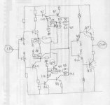
BTW, the schematic below also incorporated a clamping FB loop (Q7, Q8 plus diodes), which, as mentioned before, does not work (David ask me to investigate that).
As for my latest design, please, have some patience with me while updating my new website. As soon as it is fit to be seen I'll let you know.
Cheers, Edmond.
andy_c said:Hi Edmond,
I originally had problems with this in the Blameless design as well. This was with a PNP input stage and NPN VAS. When the clamping diode turns on, there is nothing to limit the current in the VAS on the negative half cycle of the output voltage. The positive half cycle is okay. The fix is to put a current limiter in the VAS. A small emitter resistor in the VAS, with the standard current-limiting transistor, fixes the problem. I chose the emitter resistor to get symmetrical current swing from the VAS. That is, the maximum current should be limited to 2 * Ibias.
BTW, I'm also interested in seeing your latest design.
Hi Andy,
You're right, preliminary versions of the blameless amplifier appear to have a serious omission: a current limiter. Luckily, D. Self corrected himself in later versions by including such limiter (see Q13).
BTW, the schematic below also incorporated a clamping FB loop (Q7, Q8 plus diodes), which, as mentioned before, does not work (David ask me to investigate that).
As for my latest design, please, have some patience with me while updating my new website. As soon as it is fit to be seen I'll let you know.
Cheers, Edmond.
Attachments
Re: Re: Re: CFB clamp
Hi Edmond,
I built a very similar circuit twenty years ago, I do not remember the exact details (I think of resistors in the clamping feedback loop) and it worked.
The drawing mentions that it is unstable. No way to get rid of that ?
Cheers
Edmond Stuart said:
BTW, the schematic below also incorporated a clamping FB loop (Q7, Q8 plus diodes), which, as mentioned before, does not work (David ask me to investigate that).
Hi Edmond,
I built a very similar circuit twenty years ago, I do not remember the exact details (I think of resistors in the clamping feedback loop) and it worked.
The drawing mentions that it is unstable. No way to get rid of that ?
Cheers
OK, I’ll stir the pot. 
Here........
http://www.diyaudio.com/forums/showthread.php?postid=1344023#post1344023
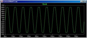
.......is the partial schematic of an amp design of mine with the VAS voltage diode clamped with a circuit that tracks the rails, thus preventing the driver and output stages from saturating. I also like to keep the voltage headroom conservative to prevent fT droop at low Vce as this allows a higher unity gain loop frequency. The circuit also provides a clipping detect output.
The circuit also has a diode clamp (unlike D.Self’s I-limiting transistor) to limit the VAS current.
Attached below is the clipping performance at 100kHz. The input stage LTP’s are being driven well into cut-off here. The LTP’s however, are a very fast stage of the amplifier and the recovery from overdrive is measurable in nano seconds.
So, the question begs:
Why should we care if the input LTP(s) is(are) driven into cut-off during clipping?
Here........
http://www.diyaudio.com/forums/showthread.php?postid=1344023#post1344023
.......is the partial schematic of an amp design of mine with the VAS voltage diode clamped with a circuit that tracks the rails, thus preventing the driver and output stages from saturating. I also like to keep the voltage headroom conservative to prevent fT droop at low Vce as this allows a higher unity gain loop frequency. The circuit also provides a clipping detect output.
The circuit also has a diode clamp (unlike D.Self’s I-limiting transistor) to limit the VAS current.
Attached below is the clipping performance at 100kHz. The input stage LTP’s are being driven well into cut-off here. The LTP’s however, are a very fast stage of the amplifier and the recovery from overdrive is measurable in nano seconds.
So, the question begs:
Why should we care if the input LTP(s) is(are) driven into cut-off during clipping?
Attachments
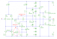
Here's my simple implementation of Edmond's CFB clamp (sorry, I mis-wrote it as CMCL)
For clear illustration, the base schematic is DartZeel schematic (CFB diamond buffer amp)
When VAS Q7-Q8 approaching 0V6 (approaching clipping), it activates Q13-Q14 to send feedback directly to inverting input (Q3-Q4 emitor).
D2-D4 to prevent reverse bias of Q13-Q14. D3//R2 to get soft characteristic. This all Edmonds idea.
The main difference with baker clamp is the clipping data is send directly to inverting input, doing this :
Kind of reducing OL gain when clipping occurs. Local anti clipping like baker clamp is doing the otherwise, pushing more and more signal during clipping.Why should we care if the input LTP(s) is(are) driven into cut-off during clipping?
Attachments
clamp
Hi Glen,
Normally, we shouldn't care about that, as a LTP is 'self limiting' , i.e. the max output current equals the tail current. But there are exceptions, the PGP amp for example. In this case, the LTP easily overdrives the next (NDFL) stage. Also in Bob's amp, in which the LTP is followed by an intermediate stage, the output has to be limited (see D2 and D3).
But we are talking about a CFB input stage, which output current is not limited by a tail current or something like that. Therefore, a simple VAS clamp is useless and we need other techniques to avoid overdrive conditions. How? See my website next week.
Cheers, Edmond.
G.Kleinschmidt said:OK, I’ll stir the pot.
[snip]
So, the question begs:
Why should we care if the input LTP(s) is(are) driven into cut-off during clipping?
Hi Glen,
Normally, we shouldn't care about that, as a LTP is 'self limiting' , i.e. the max output current equals the tail current. But there are exceptions, the PGP amp for example. In this case, the LTP easily overdrives the next (NDFL) stage. Also in Bob's amp, in which the LTP is followed by an intermediate stage, the output has to be limited (see D2 and D3).
But we are talking about a CFB input stage, which output current is not limited by a tail current or something like that. Therefore, a simple VAS clamp is useless and we need other techniques to avoid overdrive conditions. How? See my website next week.
Cheers, Edmond.
Talking about a classic VFB topology amp, I think if you can get the VAS clamping to work quickly enough, as described above, there should be no problem with the LTP being overdriven. Reason I say this is that now days, most practiioners use heavy degeneration (some like it very heavy) and this overcomes the overdrive problem. 30 years ago, you could get a nice sawtooth waveform out of a power amp because of low or no emmitter degen resistors and big Cdom caps, but those days are long gone. I jus t clamp my VAS output (its balanced design) straight to the output stage supply. The VAS stage is driven off rails that are 10V higher than the main supply rails. Of course, I'm looking forward to seeing some more elegant approaches come out of this discussion.
BTW, there is a another trick other than a classic current limiter on the voltage amp transister emmitter degen resistor as shown in Edmonds blameless design schematic. Cascode the voltage amp transistor and insert the current limiting resistor between the cascode emmitter and the voltage amp collector. This also works well on fully balanced VAS designs.
BTW, there is a another trick other than a classic current limiter on the voltage amp transister emmitter degen resistor as shown in Edmonds blameless design schematic. Cascode the voltage amp transistor and insert the current limiting resistor between the cascode emmitter and the voltage amp collector. This also works well on fully balanced VAS designs.
Re: clamp
Hi Edmond.
I agree that a CFB input stage is a different kettle of fish, but I meant in the context of applying a NFB clipping clamp to the D.Self topology, and some of the other discussion above.
In a VFB amp I think that a NFB clamp would be interesting if it was somehow incorporated with the OPS over current protection circuitry - then the need to current limit the VAS or restrict the voltage swing of any stage of the amplifier wouldn't be required at all.
Cheers,
Glen
Edmond Stuart said:
But we are talking about a CFB input stage, which output current is not limited by a tail current or something like that. Therefore, a simple VAS clamp is useless and we need other techniques to avoid overdrive conditions. How? See my website next week.
Hi Edmond.
I agree that a CFB input stage is a different kettle of fish, but I meant in the context of applying a NFB clipping clamp to the D.Self topology, and some of the other discussion above.
In a VFB amp I think that a NFB clamp would be interesting if it was somehow incorporated with the OPS over current protection circuitry - then the need to current limit the VAS or restrict the voltage swing of any stage of the amplifier wouldn't be required at all.
Cheers,
Glen
As a general comment on this business of clipping/clamping.
If the ultimate objective is to listen to music in the most linerar way, why not to adopt the following strategy:
Use an input filter and degeneration of the differential input amplifier so that there will be no slewing or transient overload there. This is well explained by Leach in his papers.
Power the Vas a little bit lower( 1v) than the ouput stage ( as side effect, this allows to filter the power supply to the Vas).
Implement a clever clipping detector/indicator in the Vas ( PIC's and optocouplers are cheap and fast enough)
Make your system with enough headroom and play without clipping indication. In this way you are sure to stay in the linear region. Of course it is brute force and power is wasted in the ouput stage, but you KNOW when you listen.
Clever circuits are nice to design but we are there in the transient/non linear area and this is difficult to analyze/simulate.
JPV
JPV,
That seems indeed sensible: turn down the volume. But with very dynamic music you probably can't avoid occasional clipping unless you listen at relatively low levels.
I do question whether you need a clipping indicator. If you don't hear it, why bother. If you do hear it, and it is too objectionable, turn it down (or get another amp ).
Question: what sort of overdrive levels are people here using to test their amp's overdrive & recovery characteristics? 6dB? 10dB?
Jan Didden
That seems indeed sensible: turn down the volume. But with very dynamic music you probably can't avoid occasional clipping unless you listen at relatively low levels.
I do question whether you need a clipping indicator. If you don't hear it, why bother. If you do hear it, and it is too objectionable, turn it down (or get another amp
).Question: what sort of overdrive levels are people here using to test their amp's overdrive & recovery characteristics? 6dB? 10dB?
Jan Didden
janneman said:JPV,
That seems indeed sensible: turn down the volume. But with very dynamic music you probably can't avoid occasional clipping unless you listen at relatively low levels.
I do question whether you need a clipping indicator. If you don't hear it, why bother. If you do hear it, and it is too objectionable, turn it down (or get another amp
Question: what sort of overdrive levels are people here using to test their amp's overdrive & recovery characteristics? 6dB? 10dB?
Jan Didden
But there is one of the major problem/
How do you know that you are listening to some fugitive clipping or harder clipping.
How do you know that this soft recovery is better than that one on any transient program.
If you have electronic crossovers, how do you know where is the clipping and for what program
An interesting note in one of Leach paper is that medium and tweeters amplifiers will see higher than expected peak voltage input transients due to the in band high pass nature of electronic crossover filters, therefore lot's of headroom requested for these amplifiers depending on efficiency of each speaker of course
There are so many parameters involved in listening that knowing my amplifiers are not clipping with my speakers is important when analyzing the total system.
I am building Linkwitz Orion speakers and hope to power them with enough headroom to avoid any clipping at more than comfortable level. That's why I am building my amps ( 10) and why I read these interesting threads.
Do you think that it is impossible to avoid clipping with realistic power amps?
Any suggestion is welcome.
Cheers
JPV
Hi, JPV,
Baker clamp does not prevent this. Edmond's CCT is working, because it reduces gain during that clipping event. During linear operation (far from rail voltages) they are off.
I tought about this also. It turns out, Edmonds CCT is not working during normal amp operation. It works only near clipping state. In this state, the transistors have big and non-linear capacitance (due to low VCE near saturation), the driver before that transistor had to push large current to that transistor, all adds up to a not normal behavior during near clipping. During clipping, worse. The differential push larger signal, high order harmonics (due to square wave formation) is happening.Clever circuits are nice to design but we are there in the transient/non linear area and this is difficult to analyze/simulate.
Baker clamp does not prevent this. Edmond's CCT is working, because it reduces gain during that clipping event. During linear operation (far from rail voltages) they are off.
JPV said:
Do you think that it is impossible to avoid clipping with realistic power amps?
Any suggestion is welcome.
Cheers
JPV
Put a DAC in the same case with the power amplifier and avoid any analog inputs. The zero digital of DAC will provide an max input voltage which won't drive into clipping the power amplifier.
JPV,
I agree that when you are setting up / designing a total system like you describe, it is very helpfull to know where / when the clipping occurs. I was referring to a normal listening situation, where a clipping indicator is not necessarily a Good Thing. Chances are that you see the indicator flashing while you are not hearing anything wrong. OTOH, so many CD sources nowadays are heavily clipped on the medium that the amp clipping becomes trivial in comparison.
I don't think you can guarantee clip-less reproduction; obviously, with a 300W amp, it will clip less than with a 30W amp. For the Orions, you surely need a hefty low freq amp, what with the significant lift at bass frequencies. I guess Siggi Linkwitz has some recommendations for it?
But, again, what level of overdrive should I test my overdrive recovery with? What's the opinion of the collected intelligence lurking here
Jan Didden
Re: Re: clamp
Hi Glen,
I think that a NFB clamp in a classical VFB amp (like the blameless) is of little use. Whether you can combine it with an over-current protection circuit, I have my doubts. There is simply too much phase shift along the chain of IPS, VAS and OPS, in particular with reactive loads.
In cases where the supply voltage of the VAS is higher than the main supply voltage, your tracking clamp will of course do the job, but I don't like such brute force method, as you effectively short circuit the output of the VAS during clamping. Just a matter of taste.
The CFB clamp however, was born when I was struggling with the finishing touch of this amp, the one with a little bit of local gain around the output stage. An attractive feature of this topology is that the supply voltage of the VAS can be chosen lower than the main supply voltage, meaning that it can be derived directly from the main PSU and regulated too without loss of voltage swing of the OPS. Also, it provides sufficient headroom for a cascode. In short, you don't need an ugly boosted PSU for the front end (in my NAD-319: 44 additional components!).
The downside is that the VAS doesn't 'know' exactly at which level it should clamp, as it depends on too may factors (main-PSU, VAS-PSU, OPS-gain, cascode-Zeners, etc). A too low level means loss of power and a too high level means it simply doesn't work.
So I concluded that the only reliable solution consists of a circuit that detects where and when it goes wrong: saturation of the drivers. Feeding the 'saturation signal' back to the VAS input is of course feasible, but in case of a fast CFB input stage, it's more elegant, even mandatory, to feed this signal back to the inverting input.
There are of course some pitfalls, for example, how to avoid additional distortion under non-clipping conditions and how to ensure that the additional FB loop doesn't affect the stability. But, according to my simulations, these issues are easily overcome.
Cheers, Edmond
G.Kleinschmidt said:Hi Edmond.
I agree that a CFB input stage is a different kettle of fish, but I meant in the context of applying a NFB clipping clamp to the D.Self topology, and some of the other discussion above.
In a VFB amp I think that a NFB clamp would be interesting if it was somehow incorporated with the OPS over current protection circuitry - then the need to current limit the VAS or restrict the voltage swing of any stage of the amplifier wouldn't be required at all.
Cheers,
Glen
Hi Glen,
I think that a NFB clamp in a classical VFB amp (like the blameless) is of little use. Whether you can combine it with an over-current protection circuit, I have my doubts. There is simply too much phase shift along the chain of IPS, VAS and OPS, in particular with reactive loads.
In cases where the supply voltage of the VAS is higher than the main supply voltage, your tracking clamp will of course do the job, but I don't like such brute force method, as you effectively short circuit the output of the VAS during clamping. Just a matter of taste.
The CFB clamp however, was born when I was struggling with the finishing touch of this amp, the one with a little bit of local gain around the output stage. An attractive feature of this topology is that the supply voltage of the VAS can be chosen lower than the main supply voltage, meaning that it can be derived directly from the main PSU and regulated too without loss of voltage swing of the OPS. Also, it provides sufficient headroom for a cascode. In short, you don't need an ugly boosted PSU for the front end (in my NAD-319: 44 additional components!).
The downside is that the VAS doesn't 'know' exactly at which level it should clamp, as it depends on too may factors (main-PSU, VAS-PSU, OPS-gain, cascode-Zeners, etc). A too low level means loss of power and a too high level means it simply doesn't work.
So I concluded that the only reliable solution consists of a circuit that detects where and when it goes wrong: saturation of the drivers. Feeding the 'saturation signal' back to the VAS input is of course feasible, but in case of a fast CFB input stage, it's more elegant, even mandatory, to feed this signal back to the inverting input.
There are of course some pitfalls, for example, how to avoid additional distortion under non-clipping conditions and how to ensure that the additional FB loop doesn't affect the stability. But, according to my simulations, these issues are easily overcome.
Cheers, Edmond
CFB clamp
Hi David,
Isn't it a bit naughty to give away my 'secret' before I've disclosed it on my website?
Cheers, Edmond.
lumanauw said:Here's my simple implementation of Edmond's CFB clamp
[snip]
Hi David,
Isn't it a bit naughty to give away my 'secret' before I've disclosed it on my website?
Cheers, Edmond.
Re: Re: Re: Re: CFB clamp
Hi Forr,
So we are/were on the same track!
I think it is feasible to make this arrangement more stable, although it'll need more components. I've tried several lead lag compensations, but without convincing results. So I prefer a CFB input stage, which is more stable, i.e. less phase shift.
Cheers, Edmond.
forr said:Hi Edmond,
I built a very similar circuit twenty years ago, I do not remember the exact details (I think of resistors in the clamping feedback loop) and it worked.
The drawing mentions that it is unstable. No way to get rid of that ?
Cheers
Hi Forr,
So we are/were on the same track!
I think it is feasible to make this arrangement more stable, although it'll need more components. I've tried several lead lag compensations, but without convincing results. So I prefer a CFB input stage, which is more stable, i.e. less phase shift.
Cheers, Edmond.
I used in the past a handy test signal that can now be used in testing non linear amplifier phenomena in a transient way, so clipping.
This signal is now also used in loudspeaker identification.
This transient is a swept signe wave ( chirp) that concentrates the energy in a defined frequency window. Of course if the signal is limited in the time domain, the spectrum is illimited in the frequency domain. But the beauty is the concentration of energy in a frequency window.
The signal s=Asin(at²+bt) for 0<t<T where T is the duration of the transient.
By choosing a, b, T we can concentrate the spectrum between f1 and f2. See the attached file obtained by FFT in Excel.
By increasing the amplitude of the transient, the non linearities of the amplifier can be excited in a transient way and in a controled way. If you then look at the spectrum outside the window f1 f2, you will have the spectrum generated by the non linearities in a transient way.
With the sound cards and the FFT softwares existing, this test is easy to implement.
I cannot compress enough the excel file. If interested I will email
Any interest
JPV
- Home
- Amplifiers
- Solid State
- Bob Cordell Interview: Negative Feedback