traderbam said:He, he, Rodolfo. I think the one truth here is that what we each consider to be blindingly obvious to others is often quite invisible.
I see you've made the acquaintance of a mirror.


Mikeks wrote:
Would you like to be introduced?I see you've made the acquaintance of a mirror.
That is idiotic and offensive.This is the problem: you blithely persist in flagrant error for hundreds of posts merely because you cannot be bothered to read posts other than your own!
mikeks said:
I see you've made the acquaintance of a mirror.
powerbecker said:My view:
Most important is that it suffers under the time delay as negativ FB also does!
This is in strong contrast to Blacks feedforward error correction.
So how ever you call it, it works not better than common NFB.
Heinz!
I believe the most important aspect of Hawksfords original FF EC
design was that it was bootstrapped inside the OP follower stage.
It was also extremely simple.
As such it is extremely -fast- and sees none of the base to collector
(tied-to-supply) capacitances.
Most of these other ideas are overly complex, don't embrace the
simple bootstrapped arrangement and as such are a lot less
elegant.
cheers
T
andy_c said:
This overshoot is also present in my design with an 8 Ohm load. I suspect it's a side-effect of the error correction.
Andy_c,
A notch filter, near the output end of your error-correction loop, might be worth trying. It was just something I decided to try, but enabled me to raise the error loop's gain by 50% to 100% and still keep the system stable.
It worked wonders in the LT-Spice opamp-based circuit that I posted here recently (which I'm still not sure qualifies as belonging to the "error-cancelling" class of systems, that has been discussed, here).
I replaced the parallel RC into the summer (R44/C4) with two Rs in series, with one similar (to before) cap all the way around the series Rs, and another (ca 3X larger) cap from the Rs' junction to gnd. I put the notch frquency somewhere between my input LPF's 3dB f and the high-freq peak of the CL response (around 580 kHz for the notch, in my case). If you try it, note that it can easily appear to make things worse, if it's not configured pretty carefully.
For the 50%-more-error-gain case, I can now get no overshoot, into 8 ohms, with a 20V p-p squarewave output (from a 1.04vp-p input w/risetime of 2.5 us), and, for larger signals, only get about 1/2 cycle of <=10% overshoot, for signals up to the limit of my +/-22v ps. At the 20vp-p and lower signal levels, all I see is some tiny (<= 40mVp-p) high-freq (1.3MHz) ripple on just the first 3 us or so of the knees of the steps. [I've just checked it for the extreme 100%-more-error-gain case, and for the 20Vp-p output I get about <=150 mVp-p of 1.2MHz ripple, lasting for about the first 10 or 12 us of each 38us squarewave top.]
Most of that sounds fairly good, BUT, at the same time, I did ALSO lower my input LPF's frequency, which accounts for a significant portion of SOME of the improvements. Eventually, I couldn't see any reason not to put it at just above 200 kHz, since this is for audio. Is that wrong? And, if I raise the LPF back up to 500 kHz, but still with the 50%-more-error-gain and notch filter setup, I do get about +700mV/-230mV of overshoot for 20Vp-p into 8 Ohms, which dies out within a little over 3 us.
I must confess that don't know the standard signal level, etc, that's used when measuring THD. I've just mostly been comparing my results with each other, usually for 20V p-p 20kHz sine output. But I wanted to give some kind of idea of what the notch filter did for the THD: With the new notch filter in the error loop (and the lowered LPF f), I was able to go from about .001% (without it) to anywhere from .0008% to .0003% THD, for 20kHz/20Vpp, depending on how much overshoot ripple I might tolerate in the step response. (And for lower frequencies and amplitudes, the THD closely-approaches that of the input signal, e.g. 4Vpp into 8 Ohms @ 20 kHz gives .000125% THD, while LT-Spice reports .000013% for the input signal, before the LPF. And for 4Vpp into 8 Ohms at 1 kHz (about 1 Watt Avg out), spice reports THD of .000007%(!), while the input's THD is reported as .000001%. For that last case, the error summer's output was only about 90 uV p-p!)
Note that I am definitely not an amplifier guru (obviously). So there probably are some thing(s) that are unrealistic, in my LT-Spice circuit. Anyone care to comment on that? It would be much-appreciated. It's still temporarily available, at http://www.fullnet.com/u/tomg/EC_Amp.asc. To actually run it, you would also need http://www.fullnet.com/u/tomg/OPA541E.SUB . Note that the downloadable version is the slightly-older one, without the magic notch filter.
The 2.2uF load IS still a problem, and, so far, requires putting the error amplifier's gain back down to where it was, at the very least (i.e. equal to the output stage's gain). But, at that gain, and with the notch filter, the square waves into 8 Ohms are basically "el perfecto".
I haven't played with this very much, yet, either. So it could probably be done in some different and better ways.
OK. Sorry to have blathered-on for so long, about all of that.
- Tom Gootee
P.S. Thanks to those of you who have directed comments my way. I sorry that I haven't had enough time, lately, to delve into this stuff far-enough to contribute or respond with anything intelligent or helpful.
(Also, "just in case", and not wanting to appear to be rude in the meantime: I will not be able to respond to any messages between later tonight and Monday morning (GMT-5).)
jcx said:Because we don’t have any such generally nullable system, you keep “forgetting” that at least one (both really for any hardware implementation) of the nulled quantities is a finite bandwidth system so the cancellation can only occur at a finite number of points where the complex frequency response having both phase and amplitude equal intersect[snip]
No I don't foprget this; I am aware of this. In a private correcpondence Ed Cherry was quick to point this out to me years ago.
I am not a trained engineer so I have to do most of my thinking myself
. Acknowledging your comment above, I don't see how this fact (that the null can only be obtained at one point) makes a difference in the discussion on whether the H.ec is 'just a fb system in disguise'. Jan Didden
Hello all, good morning again from a sunny Holland!
I have been away a few days but have been thinking on this subject nevertheless. Please allow me to take a different slant, maybe that will help to further the understanding.
I do now agree with those that state that the three topologies we have seen:
- Hawksford basic topology with a=1 and b=0;
- Brain I think it was showing a pos feedback loop followed by a non-linear gain stage, and the whole enclosed in a neg fb loop;
- My clumsy picture from my AES preprint.
.. that these are in fact equivalent.
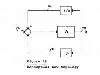
So, let my pick one - and because of my ego, I'll pick mine. (see below).
Earlier I said that for me the fundamental difference between 'normal' gfb and H.ec was the fact that gfb can never, not even in theory, null the error. H.ec can, even if it is (yes jcx) only at a specific point: it's a null network allright.
Now, what causes this crucial difference? In the attached, it is just this little extra pos feedback of a quantity inversely proportional to the gain stage's gain: this 1/A. That makes the '1' in the denominator of the cl fb gain equation disappear.
My thinking goes like this:
- If the A gain (and the nfb factor) are relatively high, the 1/A is relatively small. Does that imply that its impact on the stability of the system is also relatively small? And coversely, that if the A is small, and the nfb factor low, the 1/A has LARGE impact on stability? Does that mean the 1/A should preferably be used with high gain/high feedback, although probably here it's effect is relatively small? (I guess we need a sensitivity analysis actually).
- Given that the 'null' produced by H.ec is only effective at a certain point in the transfer function, will this null be broader (and thus its effect more advantageous) if we use H.ec in a system with high A and high nfb that is already quite linear?And vice versa?
Jan Didden
I have been away a few days but have been thinking on this subject nevertheless. Please allow me to take a different slant, maybe that will help to further the understanding.
I do now agree with those that state that the three topologies we have seen:
- Hawksford basic topology with a=1 and b=0;
- Brain I think it was showing a pos feedback loop followed by a non-linear gain stage, and the whole enclosed in a neg fb loop;
- My clumsy picture from my AES preprint.
.. that these are in fact equivalent.
So, let my pick one - and because of my ego, I'll pick mine. (see below).
Earlier I said that for me the fundamental difference between 'normal' gfb and H.ec was the fact that gfb can never, not even in theory, null the error. H.ec can, even if it is (yes jcx) only at a specific point: it's a null network allright.
Now, what causes this crucial difference? In the attached, it is just this little extra pos feedback of a quantity inversely proportional to the gain stage's gain: this 1/A. That makes the '1' in the denominator of the cl fb gain equation disappear.
My thinking goes like this:
- If the A gain (and the nfb factor) are relatively high, the 1/A is relatively small. Does that imply that its impact on the stability of the system is also relatively small? And coversely, that if the A is small, and the nfb factor low, the 1/A has LARGE impact on stability? Does that mean the 1/A should preferably be used with high gain/high feedback, although probably here it's effect is relatively small? (I guess we need a sensitivity analysis actually).
- Given that the 'null' produced by H.ec is only effective at a certain point in the transfer function, will this null be broader (and thus its effect more advantageous) if we use H.ec in a system with high A and high nfb that is already quite linear?And vice versa?
Jan Didden
Attachments

Hi, AndyC,
I don't know if you have revised your opinion about EC, but the above quote makes me think alot.
What happened if the EC tries to compensate for the nature rolling down response of the output stage? I think it is very possible, because the EC transistors usually smaller size (have much higher fT) than the output transistors.
But one problem is that the loop in its
idealized form tries to force the output to equal the input independent of frequency.
So at high frequencies, large error correction voltages will appear that are compensating
for frequency response effects. In the ideal case, you'd want to low-pass filter
the picked-off input of the output stage with a filter that very closely matches
the frequency response of the output stage, prior to subtracting it from the picked-off
output to get the error voltage
I don't know if you have revised your opinion about EC, but the above quote makes me think alot.
What happened if the EC tries to compensate for the nature rolling down response of the output stage? I think it is very possible, because the EC transistors usually smaller size (have much higher fT) than the output transistors.
Good morning Jan! A nice positive start to the day. 
If there is a specific point where the output error is zero with H.ec, then there will also be a specific point with NFB where the error is zero...and it will be the same point. If they are the same.
They are either the same or they are not.
Which is it going to be?
Hmm...more on this later.I do now agree with those that state that the three topologies we have seen... that these are in fact equivalent.
I think you have to decide whether or not the two are the same. You said that you are now sure that the H.ec diagram and my NFB diagram are the same. But you then say one has a different property to the other.Earlier I said that for me the fundamental difference between 'normal' gfb and H.ec was the fact that gfb can never, not even in theory, null the error. H.ec can, even if it is (yes jcx) only at a specific point: it's a null network allright.
If there is a specific point where the output error is zero with H.ec, then there will also be a specific point with NFB where the error is zero...and it will be the same point. If they are the same.
They are either the same or they are not.
Which is it going to be?
traderbam said:[snip]I think you have to decide whether or not the two are the same. You said that you are now sure that the H.ec diagram and my NFB diagram are the same. But you then say one has a different property to the other.
If there is a specific point where the output error is zero with H.ec, then there will also be a specific point with NFB where the error is zero...and it will be the same point. If they are the same.
They are either the same or they are not.
Which is it going to be?
OK, I'll try to be more specific/clear:
They are the same, all three are a combination of pos fb and nfb. The three are therefore fundamentally different from a nfb-only loop because in the three equivalent topologies, the addition of the pfb (the 1/A in my case) makes that the error can be nulled, which is not the case in the nfb-only case.
So I agree with you that each of the three cases, including the H.ec, is a combination of pfb and nfb. Do you agree that the addition of the 1/A pfb is a significant difference? (And we can talk about whether it is worthwhile or not later).
Jan Didden
mikeks said:
Where?
Must have missed it.
It probably stems from the fact - as perspiring from your posts then - you allways implicitly assummed an unity gain (ef, sf) output stage as the one to be corrected.
Perhaps you may want to check again my origina pdf and the sequel of posts, in particular where you insisted the 1/A' attenuator was not required and my responses.
I allways had in mind correction of the whole amplifier, so I made room for a reasonable gain, 20 dB is what I built in fact. In the pdf you will notice both for the conventional negative feedback and error correction scheme, the amplifier to be corrected is treated equally.
Rodolfo
Jan, I feel the penny is going to drop very shortly...so let's persist.
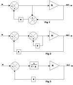
I am saying that figures 1, 2 and 3 (below) are equivalent. Fig 1 is H.ec as shown in his model. Fig 3 is a normal NFB system.
If they are all the same, if fig 1 can be nulled, so can fig 3.
Disagree.the addition of the pfb (the 1/A in my case) makes that the error can be nulled, which is not the case in the nfb-only case.
I am saying that figures 1, 2 and 3 (below) are equivalent. Fig 1 is H.ec as shown in his model. Fig 3 is a normal NFB system.
If they are all the same, if fig 1 can be nulled, so can fig 3.
No.Do you agree that the addition of the 1/A pfb is a significant difference?
Attachments
- Home
- Amplifiers
- Solid State
- Bob Cordell Interview: Error Correction