Clipping indicators
Actually, the best clipping indicator is probably the I-O compare. The output is scaled down to the input level, and the input signal is passed through a delay that approximates the HF rolloff of the amplifier. The two are subtracted, producing what is nominally a null. If the amplitude of this signal increases beyond a certain point, clipping is assumed. This circuit covers the possibility that the amplifier will clip in the current domain, or protect. This circuit may also detect a brief burst of parasitic oscillation if it is done carefully. Of course, the output indication should include a monostable to prolong the indication of clipping (or, more generally, "misbehavior").
In some cases it is possible, albeit more intrusive, to effectively utilize the amplifier's input differential pair to do the above-mentioned subtraction and comparison.
For example, in my MOSFET power amplifier, I have a paralleled doide pair across the outputs of the cascoded input differential pair to prevent saturation and over-swing in a clipping situation. If these catch diodes are replaced with transistors whose collector current is monitored for conduction, a clipping indication can be derived. There are often numerous places in the forward signal path where indications of clipping can be derived.
Bob
Upupa Epops said:Best clipping indicator is based on window comparator, which compare both rail voltage and output voltage, folloved by monostabil " delay " comparator, which extend output pulse ( human eye have big inertia and short flash of lightning can't perceive ).
Actually, the best clipping indicator is probably the I-O compare. The output is scaled down to the input level, and the input signal is passed through a delay that approximates the HF rolloff of the amplifier. The two are subtracted, producing what is nominally a null. If the amplitude of this signal increases beyond a certain point, clipping is assumed. This circuit covers the possibility that the amplifier will clip in the current domain, or protect. This circuit may also detect a brief burst of parasitic oscillation if it is done carefully. Of course, the output indication should include a monostable to prolong the indication of clipping (or, more generally, "misbehavior").
In some cases it is possible, albeit more intrusive, to effectively utilize the amplifier's input differential pair to do the above-mentioned subtraction and comparison.
For example, in my MOSFET power amplifier, I have a paralleled doide pair across the outputs of the cascoded input differential pair to prevent saturation and over-swing in a clipping situation. If these catch diodes are replaced with transistors whose collector current is monitored for conduction, a clipping indication can be derived. There are often numerous places in the forward signal path where indications of clipping can be derived.
Bob
andy_c said:


Upupa Epops said:The best clipping indicator is based on window comparator, which compare both rail voltage and output voltage, followed by monostable "delay" comparator, which extends the output pulse.
This also was my view, although i have never designed one.
Certainly i would agree that the assumption that the supply rails are fixed is not tenable; the reference would have to be ''bootstrapped'' to the supply rail(s).
From an admittedly cursory examination, i am not not sure this is accommodated, with precision, by Leach's offering.

sam9 said:Monitoring the differential pair should allow for more than just clipping detection but allow detection of any distortion above a particular level.
The problem with this, i suspect, is clipping in the input stage (current swing entirely from one transistor to the other) is not necessarily related to voltage clip in subsequent stages.
Hi Mike,
Actually, monitoring the input stage differential is an excellent way to monitor for any condition that the input stage can not correct for. McIntosh uses this in it's "power guard" protection circuit. I've had a chance to play with it and it does in fact work well.
-Chris
Actually, monitoring the input stage differential is an excellent way to monitor for any condition that the input stage can not correct for. McIntosh uses this in it's "power guard" protection circuit. I've had a chance to play with it and it does in fact work well.
-Chris
Hi Chris,
This is an undoubtedly an excellent way of establishing if the first stage is in current clip.
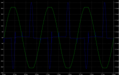
But the amp. may be driven to voltage clip at its output, without causing the former:
Blue trace: Current in one of diff stage BJTsm (tail-current~4mA).
Green trace: Output voltage.
In other words, this approach will not detect clipping at the output, and is, therefore, fundamentally flawed.
This is an undoubtedly an excellent way of establishing if the first stage is in current clip.
But the amp. may be driven to voltage clip at its output, without causing the former:
Blue trace: Current in one of diff stage BJTsm (tail-current~4mA).
Green trace: Output voltage.
In other words, this approach will not detect clipping at the output, and is, therefore, fundamentally flawed.
Attachments
anatech said:Hi Mike,
Actually, monitoring the input stage differential is an excellent way to monitor for any condition that the input stage can not correct for. McIntosh uses this in it's "power guard" protection circuit. I've had a chance to play with it and it does in fact work well.
-Chris
Have you got the McIntosh schematic?
Hi Mike,
No, but their car amps used it as well as the home amps. They monitor both inputs, which is what I intended. If the differential inputs are out of range the amplifier is definitely not operating in a linear mode.
I lost all my manuals when I sold my shop about 9 years ago.

Imagine an op amp used as the voltage amp. Hang another op amp across the terminals in the same way (+ input to + input, etc). Then monitor the output of the second op amp. It will output a large signal and clip whenever the other op amp can't balance it's inputs.
I haven't tried this with normal transistor type diff pairs, but it might be interesting in a DIY sense. McIntosh most certainly has patented this idea (I would think).
-Chris
No, but their car amps used it as well as the home amps. They monitor both inputs, which is what I intended. If the differential inputs are out of range the amplifier is definitely not operating in a linear mode.
I lost all my manuals when I sold my shop about 9 years ago.
Imagine an op amp used as the voltage amp. Hang another op amp across the terminals in the same way (+ input to + input, etc). Then monitor the output of the second op amp. It will output a large signal and clip whenever the other op amp can't balance it's inputs.
I haven't tried this with normal transistor type diff pairs, but it might be interesting in a DIY sense. McIntosh most certainly has patented this idea (I would think).
-Chris
anatech said:They monitor both inputs, which is what I intended.
-Chris
True.
mikeks said:
I wouldn't worry too much about your lack of experience, old chap.
I think you mistook the thought behind the comment.
mikeks said:As we've seen much too often on this forum, it's not so much time served as what is learnt from that experience that is important.
Way too many folk have a lot of ''experience'' without actually learning much that is true in fact.
Then there is also folks who hide behind fact and take a narrowminded approach to anything that doesn't fall within their understanding of the truth.
There is no substitute actually building an idea and then trying to understand what it's doing by listening. (which is, afterall, what this is all about.
I bet the results don't align with the theory at times. Although the other way is much easier.
Regards, Mike.
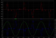
mikeks said:However, if the intention is to monitor the input error voltage (red trace) for unusually large spikes, then, as Bob has pointed out, this may be a workable approach.
Mike, your simulations are both showing that it is easy to detect output clipping from those input waveforms.
You might notice a very low amplitude sinewave shape of about 10 mV amplitude in the red trace, until the clipping starts, then the large (>100mV peak) half sine looking peaks are seen. This is the input stage trying, and failing to correct for the clipping. Similar half sine peaks can be seen in the current waveform.
Note the small blips aligned with the output zero crossing which are the input stage correcting for crossover distortion.
If you reduce the input level until there is no clipping I'd expect that you'll see a clean ~10mV sine, with blips at the zero crossings.
Comparing the input differential voltage, or current to a threshold value does work.
Pete B.
MikeBettinger said:Then there is also folks who hide behind fact and take a narrowminded approach to anything that doesn't fall within their understanding of the truth.
Don't be too hard on yourself old chap.
Gentlemen;
the purpose of the Klipper is to clip instead of the power amp on level right below it's clipping. What I did, I put couple of diodes in the constant temperature about 60 degrees C, and monitoring current through them detected point when they start clipping providing visible signal in addition to the audible distortions. What Bob did in his design, he made the level dependent on available power voltage to squeeze all available headroom from the amp depending on power line conditions.
the purpose of the Klipper is to clip instead of the power amp on level right below it's clipping. What I did, I put couple of diodes in the constant temperature about 60 degrees C, and monitoring current through them detected point when they start clipping providing visible signal in addition to the audible distortions. What Bob did in his design, he made the level dependent on available power voltage to squeeze all available headroom from the amp depending on power line conditions.
PB2 said:
Mike, your simulations are both showing that it is easy to detect output clipping from those input waveforms.
You might notice a very low amplitude sinewave shape of about 10 mV amplitude in the red trace, until the clipping starts, then the large (>100mV peak) half sine looking peaks are seen. This is the input stage trying, and failing to correct for the clipping. Similar half sine peaks can be seen in the current waveform.
Note the small blips aligned with the output zero crossing which are the input stage correcting for crossover distortion.
If you reduce the input level until there is no clipping I'd expect that you'll see a clean ~10mV sine, with blips at the zero crossings.
Comparing the input differential voltage, or current to a threshold value does work.
Pete B.
You're right about the input error voltage-i misunderstood Chris.
As for the current peaks, you may have a point: after all an anomalous increase in error voltage must necessarily lead to an accompanying increase in current in one or other of the Diff. stage BJTs.
Any concrete ideas in respect of circuitry?
Hi Bob,
Thanks for your reply.
---Yes, the Peak-Average display box was a very big hit at the Rocky Mountain Audio Fest. A number of people wanted one. I'd be interested in knowing how much interest there is out there.---
I am interested.
I remember the clipping indicator of my DB6 amplifier (40 W RMS, DB Systems, David Hadaway ?). The idea is very nice : a bipolar transistor has its base connected to a voltage referenced to one of the power supply rails (a PNP for Vccpos). Its emitter is connected through a diode to the voltage amplification stage. The transistor is normaly blocked until the voltage at the VAS approaches the voltage given by Vccpos - Vref + Vbe + Vd. Then it starts to conduct and to steal some current from the Vas stage. There is an other transistor dealing with the negative voltage excursions. The collector currents can be used for many applications.
Used with BBC LS3/5A's for three years, the DB6 clipping indicator never flashed.
PB2 said:
Mike, your simulations are both showing that it is easy to detect output clipping from those input waveforms.
The required difference (error) in either current or voltage may be as small as 50uA, or 3.5mV: an op amp. may be required to amplify this....before applying it to a comparator...
- Home
- Amplifiers
- Solid State
- Bob Cordell Interview: Error Correction