
Re: Non-HEC-amp
Nice work, Edmond. I'll need a little bit of time to absorb it all.
Cheers,
Bob
Edmond Stuart said:
Hi Bob,
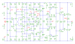
Here's the simplified schematic of my amp with the NFB output stage.
And here are some key figures, where Fc is the unity gain frequency of a loop, PM the phase margin and GM the gain margin.
Output stage: Fc = 2.9MHz, PM = 76 deg., GM = 26dB
Global FB loop: Fc = 900kHz, PM = 87 deg., GM = 21dB
Miller loop: Fc = 9MHz, PM = 73 deg., GM = 6dB
CMCL: Fc = 350kHz, PM = 64 deg., GM = 45 dB
TMC: Fc = 1MHz.
Slew rate: 200V/us.
THD20 at 50W: 0.65ppm, at 100W: 0.9ppm (into 8 Ohm, BW=100kHz)
In the next posts I'll show the distortion spectra and the (slightly) improved step response.
Cheers, Edmond.
Nice work, Edmond. I'll need a little bit of time to absorb it all.
Cheers,
Bob
Re: Re: Non-HEC-amp
Hi Bob,
Thanks and take your time.
Cheers, Edmond.
Bob Cordell said:
Nice work, Edmond. I'll need a little bit of time to absorb it all.
Cheers,
Bob
Hi Bob,
Thanks and take your time.
Cheers, Edmond.
Re: Non-HEC-amp
Hi Edmond
Nice VAS! Virtually identical to what I am using, but mine is prettier because I use pretty LEDs to bias the Hawksford cascodes.
Here is my simmed THD-20 delivering 100W into 8 ohms (100kHz BW) with a plain-straight class AB bipolar output stage:
No CMCL, 3k LTP loads and the TMC wrapping up the VAS. I've found compensating the amp this way to give better THD performance in this configuration due to the linearization (if that is a word) of the VAS by the tight pair of nfb loops.
Of course, the slew rate isn't as good, but I can run the LTP's a little hot an get an easy 100V/us in a non-bridge design.
How much does your amps overall THD go up if you delete the CMCL completely and just load the IPS with 3k resistors?
Cheers,
Glen
Edmond Stuart said:
Hi Bob,
Is it really that hard to get my point? It doesn't matter what you know, the point is what the EC point of view (without any knowledge of other points of view and practical experience) has to offer. Never mind, so let's go to business.
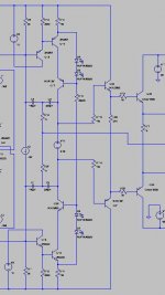
Here's the simplified schematic of my amp with the NFB output stage. As you can see, the input stage as well as the output stage utilizes current feedback and the bias of the symmetrical VAS is stabilized by a common mode control loop (Q7,12,13,14)
Just as in your design, the 'Miller' compensation is applied between the VAS output and the inverting input of the IPS.
Despite the fact that a CFB IPS is faster than a LTP, also in this design it was necessary to add one more pole and zero (C3,R26, resp. C5,R27) to get the front-end stable.
As we all know, the Early effect isn't accurately modeled by most simulators. So, to be on the safe side, I've eliminated this effect completely by bootstrapping (R10,11,etc,) and by using CF cascodes (Q8,11,18,19), Maybe it's superfluous. OTOH, the added cost is virtual nihil. BTW, the THD20 of the front-end with this arrangement is only 10ppb.
The TMC network consists of C9, R35 and R35.
And here are some key figures, where Fc is the unity gain frequency of a loop, PM the phase margin and GM the gain margin.
Output stage: Fc = 2.9MHz, PM = 76 deg., GM = 26dB
Global FB loop: Fc = 900kHz, PM = 87 deg., GM = 21dB
Miller loop: Fc = 9MHz, PM = 73 deg., GM = 6dB
CMCL: Fc = 350kHz, PM = 64 deg., GM = 45 dB
TMC: Fc = 1MHz.
Slew rate: 200V/us.
THD20 at 50W: 0.65ppm, at 100W: 0.9ppm (into 8 Ohm, BW=100kHz)
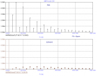
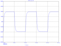
In the next posts I'll show the distortion spectra and the (slightly) improved step response.
Cheers, Edmond.
Hi Edmond
Nice VAS! Virtually identical to what I am using, but mine is prettier because I use pretty LEDs to bias the Hawksford cascodes.
Here is my simmed THD-20 delivering 100W into 8 ohms (100kHz BW) with a plain-straight class AB bipolar output stage:
Code:
Harmonic	Frequency	 Fourier 	Normalized	 Phase  	Normalized
 Number 	  [Hz]   	Component	 Component	[degree]	Phase [deg]
    1   	2.000e+04	4.000e+01	1.000e+00	   -0.89°	    0.00°
    2   	4.000e+04	2.211e-06	5.527e-08	   44.98°	   45.87°
    3   	6.000e+04	1.013e-04	2.532e-06	 -153.06°	 -152.17°
    4   	8.000e+04	1.510e-05	3.776e-07	  179.36°	  180.25°
Total Harmonic Distortion: 0.000256%
No CMCL, 3k LTP loads and the TMC wrapping up the VAS. I've found compensating the amp this way to give better THD performance in this configuration due to the linearization (if that is a word) of the VAS by the tight pair of nfb loops.
Of course, the slew rate isn't as good, but I can run the LTP's a little hot an get an easy 100V/us in a non-bridge design.
How much does your amps overall THD go up if you delete the CMCL completely and just load the IPS with 3k resistors?
Cheers,
Glen
Attachments
Hi, Edmond,
This VAS is new to me. Besides controling bias current, is this arrangement (local feedback loop between Q15-Q13-Q7) have some effect on linearity of Q17 (VAS transistor)?
and the bias of the symmetrical VAS is stabilized by a common mode control loop (Q7,12,13,14)
This VAS is new to me. Besides controling bias current, is this arrangement (local feedback loop between Q15-Q13-Q7) have some effect on linearity of Q17 (VAS transistor)?
Re: Re: Non-HEC-amp
Hi Glen,
Your THD results are really impressive for a class-AB amp. Do you have abandoned class-heat? And how high is the total quiescent current of the OPS?
I'm not sure whether biasing the Hawksford cascodes with LEDs is better, as I (and others) have observed that without base stopper resistors, such cascodes tend to instability. Therefore I have deliberately used resistors in stead of LEDs or zeners. For the same reason R15 and R15 are not bypassed by a cap. Notice that Q8 and Q11 are Hawksford cascodes in disguise!
Loading the IPS by 3k raises the THD20 by as much as ten times.
Cheers, Edmond.
NB: Please Glen, change the default settings of LTSpice, nobody, including Rachel, can't read your schematics and it looks terrible. So set the background to white and increase the font size.
G.Kleinschmidt said:Hi Edmond
Nice VAS! Virtually identical to what I am using, but mine is prettier because I use pretty LEDs to bias the Hawksford cascodes.
Here is my simmed THD-20 delivering 100W into 8 ohms (100kHz BW) with a plain-straight class AB bipolar output stage:
Code:Harmonic Frequency Fourier Normalized Phase Normalized Number [Hz] Component Component [degree] Phase [deg] 1 2.000e+04 4.000e+01 1.000e+00 -0.89° 0.00° 2 4.000e+04 2.211e-06 5.527e-08 44.98° 45.87° 3 6.000e+04 1.013e-04 2.532e-06 -153.06° -152.17° 4 8.000e+04 1.510e-05 3.776e-07 179.36° 180.25° Total Harmonic Distortion: 0.000256%
No CMCL, 3k LTP loads and the TMC wrapping up the VAS. I've found compensating the amp this way to give better THD performance in this configuration due to the linearization (if that is a word) of the VAS by the tight pair of nfb loops.
Of course, the slew rate isn't as good, but I can run the LTP's a little hot an get an easy 100V/us in a non-bridge design.
How much does your amps overall THD go up if you delete the CMCL completely and just load the IPS with 3k resistors?
Cheers,
Glen
Hi Glen,
Your THD results are really impressive for a class-AB amp. Do you have abandoned class-heat? And how high is the total quiescent current of the OPS?
I'm not sure whether biasing the Hawksford cascodes with LEDs is better, as I (and others) have observed that without base stopper resistors, such cascodes tend to instability. Therefore I have deliberately used resistors in stead of LEDs or zeners. For the same reason R15 and R15 are not bypassed by a cap. Notice that Q8 and Q11 are Hawksford cascodes in disguise!
Loading the IPS by 3k raises the THD20 by as much as ten times.
Cheers, Edmond.
NB: Please Glen, change the default settings of LTSpice, nobody, including Rachel, can't read your schematics and it looks terrible. So set the background to white and increase the font size.
lumanauw said:Hi, Edmond,
This VAS is new to me. Besides controling bias current, is this arrangement (local feedback loop between Q15-Q13-Q7) have some effect on linearity of Q17 (VAS transistor)?
Hi lumanauw,
Actually, it is not really new, as the same principle is used in our PGP amp. Regarding linearity of the VAS, it has a slight (positive) effect.
Cheers, Edmond.
Hi, Edmond,
Discussing about VAS drive, what is your opinion about this kind of VAS drive? This is from SKA topology. It boost the gain of the VAS drive, (making it high impedance) by using bootstrap (R2+R3+C2). Then feeded to emitor follower Q5. From here, it drives the VAS stage (Q7-Q8, but here Q7-Q8 are already power devices).
Discussing about VAS drive, what is your opinion about this kind of VAS drive? This is from SKA topology. It boost the gain of the VAS drive, (making it high impedance) by using bootstrap (R2+R3+C2). Then feeded to emitor follower Q5. From here, it drives the VAS stage (Q7-Q8, but here Q7-Q8 are already power devices).
Attachments
Re: Re: Re: Non-HEC-amp
Hi Edmond
Bias is a hefty 450mAand 3 bipolar pairs are used. I haven’t abandoned class-A; this is just a play in spice. WRT Hawksford cascode biasing, I agree that the benefits of LED biasing are marginal; I only claimed that my VAS was prettier
As for parasitic oscillation of the cascode device, this has never been a problem for me in simulation so I haven’t bothered to add base stoppers to the cascode devices in my spice circuits.
Also, in the few I’ve actually built, oscillations haven’t been a problem either. The only time I’ve had a problem with such a cascode (on a VAS transistor) is when one I built while phototyping was driven into saturation, which was then fixed with an anti-saturation clamp.
If they ever do show a tendency to oscillation, my preferred fix would be to snip the base lead of the TO-92 or TO-126 cascode device close to the package, about ~4mm above the PCB, and to solder in series a miniature 1/8W axial ‘base stopper’ resistor. This should work fine with either LED or voltage reference (I’ve used LM336 too) biasing.
So with 3k load resistors your THD-20 for 100W into 8 ohms rises to about 0.001% Hmmmmm……
That’s reasonably high for a TMC amp with such a low distortion OPS.
I’m running my degenerated complementary input LTP’s with a hefty tail current of 8mA, all of which is available for driving the 3k load/VAS-biasing resistors (and the VAS miller capacitance) in push-pull due to the current mirror loads. I guess this, in part, is why my IPS may be less sensitive (THD wise) to loading than yours.
Cheers,
Glen.
BTW, I asked Rachel to look at my schematics. Besides protesting that it’s not my big schematics that she’s interested in (women do have rather one-tracked minds, you know?), she said that they look perfectly legible and suggests that you need better spectacles.
Edmond Stuart said:
Hi Glen,
Your THD results are really impressive for a class-AB amp. Do you have abandoned class-heat? And how high is the total quiescent current of the OPS?
I'm not sure whether biasing the Hawksford cascodes with LEDs is better, as I (and others) have observed that without base stopper resistors, such cascodes tend to instability. Therefore I have deliberately used resistors in stead of LEDs or zeners. For the same reason R15 and R15 are not bypassed by a cap. Notice that Q8 and Q11 are Hawksford cascodes in disguise!
Loading the IPS by 3k raises the THD20 by as much as ten times.
Cheers, Edmond.
NB: Please Glen, change the default settings of LTSpice, nobody, including Rachel, can't read your schematics and it looks terrible. So set the background to white and increase the font size.
Hi Edmond
Bias is a hefty 450mAand 3 bipolar pairs are used. I haven’t abandoned class-A; this is just a play in spice. WRT Hawksford cascode biasing, I agree that the benefits of LED biasing are marginal; I only claimed that my VAS was prettier
As for parasitic oscillation of the cascode device, this has never been a problem for me in simulation so I haven’t bothered to add base stoppers to the cascode devices in my spice circuits.
Also, in the few I’ve actually built, oscillations haven’t been a problem either. The only time I’ve had a problem with such a cascode (on a VAS transistor) is when one I built while phototyping was driven into saturation, which was then fixed with an anti-saturation clamp.
If they ever do show a tendency to oscillation, my preferred fix would be to snip the base lead of the TO-92 or TO-126 cascode device close to the package, about ~4mm above the PCB, and to solder in series a miniature 1/8W axial ‘base stopper’ resistor. This should work fine with either LED or voltage reference (I’ve used LM336 too) biasing.
So with 3k load resistors your THD-20 for 100W into 8 ohms rises to about 0.001% Hmmmmm……
That’s reasonably high for a TMC amp with such a low distortion OPS.
I’m running my degenerated complementary input LTP’s with a hefty tail current of 8mA, all of which is available for driving the 3k load/VAS-biasing resistors (and the VAS miller capacitance) in push-pull due to the current mirror loads. I guess this, in part, is why my IPS may be less sensitive (THD wise) to loading than yours.
Cheers,
Glen.
BTW, I asked Rachel to look at my schematics. Besides protesting that it’s not my big schematics that she’s interested in (women do have rather one-tracked minds, you know?), she said that they look perfectly legible and suggests that you need better spectacles.
Re: Re: Re: Re: Non-HEC-amp
- Klaus
Oh, c'mon... being a gentlemen you might use a lossless graphics format like 256-color .gif instead of .jpg. The latter was never meant to be used with computer graphics (it's intended for real photographs).G.Kleinschmidt said:BTW, I asked Rachel to look at my schematics. Besides protesting that it’s not my big schematics that she’s interested in (women do have rather one-tracked minds, you know?), she said that they look perfectly legible and suggests that you need better spectacles.
- Klaus
Impressive numbers you have there, Edmond. While I (think I) understand most of the circuit pretty well, the gain stage is a bit tricky and refuses to get easily absorbed in my head...Edmond Stuart said:Actually, it is not really new, as the same principle is used in our PGP amp. Regarding linearity of the VAS, it has a slight (positive) effect.
Uhm, does THD20 rise when output current is close to the A/B transition, say at 300mA? And does it change when, at these output current levels, the output voltage is varied, especially when coming closer to the rails? This I always find interesting to see, given the (more or less) uncorrelated nature of output voltage vs. output current with real speakers.
In this regard I find a very informative "plot" the following one (just in imagination, in reality hard to obtain and plot):
small signal output impedance vs. steady state output current, output voltage and frequency. That is a 3D scalar field, the "impedance magnitude potential" (or a vector field if we take the complex impedance). If that potential is constant, the amp could be distortionless (I think this is a required condition for that), and if any changes are smooth low order functions, the distortion character (and changes thereof) is benign. Also one could examine a series of these plots in time, with varying large signal/power conditions, that would bring the memory aspect in again.... just a little theory of mine...
Regards, Klaus
Jan wrote:
Jan, this would be a true advantage of the HEC topology and ought to be highlighted if it can be objectively demonstrated.
I assume that the FB factor is the product of forward gain and FB path gain. In your classical FB case the forward gain is 70dB and the FB factor is 26dB so this implies the FB path gain is -44dB. In the HEC case the forward gain is 26dB and the FB factor is 26dB so the FB path gain is 0dB. The two cases have quite different CL gains so I'm not sure they are comparable in the way you intend.
Suppose I were to rephrase the question: If the two amps have the same CL gain (say 0dB) and the same FB factor (say 26dB), is one more prone to clipping/slew limiting than the other?
Is that is a fair way to pose the question? If so I can answer it objectively.
Ever since Otala (and even before) we have been aware of internal amplifier overshoot, slew rate limiting etc, phenomena that are generally ascribed to high internal (ol) gain. So I wonder if one of the so far not mentioned advantages of HEC, with a low ol gain forward path, might be a (much) lesser susceptibility to these issues. I know that these issues can be adequately taken care of in a 'classical' nfb amp; I'm just trying to find if there are possible differences in this regard that have not yet be mentioned.
For example, the case of clipping. Suppose that Vout falls 5V short of the undistorted output due to clipping. With a classical feedback factor of 20, that means an additional 0.25V input signal to an amp that perhaps has 70dB open loop gain, so we need to be carefull to handle this overdrive.
In the cas of HEC with say an ol gain of 20 and a nfb factor also 20, we would have the same additional 0.25 input voltage from the nfb loop, but now our ol gain is only 20 so I would expect the overdrive etc to be a lesser issue.
Jan, this would be a true advantage of the HEC topology and ought to be highlighted if it can be objectively demonstrated.
I assume that the FB factor is the product of forward gain and FB path gain. In your classical FB case the forward gain is 70dB and the FB factor is 26dB so this implies the FB path gain is -44dB. In the HEC case the forward gain is 26dB and the FB factor is 26dB so the FB path gain is 0dB. The two cases have quite different CL gains so I'm not sure they are comparable in the way you intend.
Suppose I were to rephrase the question: If the two amps have the same CL gain (say 0dB) and the same FB factor (say 26dB), is one more prone to clipping/slew limiting than the other?
Is that is a fair way to pose the question? If so I can answer it objectively.
Re: Re: Non-HEC-amp
Nice work, Brian.
I take it this is Class AB with about 150 mA bias using OnSemi RETs and maybe 0.1 ohm RE and no EC, right?
What was the gain crossover frequency of the NFB?
This seems to speak well for TMC's ability to reduce output stage distortion. How much would the distortion be if you did not use TMC, but used the same NFB gain-crossover frequency?
Thanks for sharing this with us.
Cheers,
Bob
G.Kleinschmidt said:
Hi Edmond
Nice VAS! Virtually identical to what I am using, but mine is prettier because I use pretty LEDs to bias the Hawksford cascodes.
Here is my simmed THD-20 delivering 100W into 8 ohms (100kHz BW) with a plain-straight class AB bipolar output stage:
Code:Harmonic Frequency Fourier Normalized Phase Normalized Number [Hz] Component Component [degree] Phase [deg] 1 2.000e+04 4.000e+01 1.000e+00 -0.89° 0.00° 2 4.000e+04 2.211e-06 5.527e-08 44.98° 45.87° 3 6.000e+04 1.013e-04 2.532e-06 -153.06° -152.17° 4 8.000e+04 1.510e-05 3.776e-07 179.36° 180.25° Total Harmonic Distortion: 0.000256%
No CMCL, 3k LTP loads and the TMC wrapping up the VAS. I've found compensating the amp this way to give better THD performance in this configuration due to the linearization (if that is a word) of the VAS by the tight pair of nfb loops.
Of course, the slew rate isn't as good, but I can run the LTP's a little hot an get an easy 100V/us in a non-bridge design.
How much does your amps overall THD go up if you delete the CMCL completely and just load the IPS with 3k resistors?
Cheers,
Glen
Nice work, Brian.
I take it this is Class AB with about 150 mA bias using OnSemi RETs and maybe 0.1 ohm RE and no EC, right?
What was the gain crossover frequency of the NFB?
This seems to speak well for TMC's ability to reduce output stage distortion. How much would the distortion be if you did not use TMC, but used the same NFB gain-crossover frequency?
Thanks for sharing this with us.
Cheers,
Bob
KSTR said:Impressive numbers you have there, Edmond. While I (think I) understand most of the circuit pretty well, the gain stage is a bit tricky and refuses to get easily absorbed in my head...
Uhm, does THD20 rise when output current is close to the A/B transition, say at 300mA? And does it change when, at these output current levels, the output voltage is varied, especially when coming closer to the rails? This I always find interesting to see, given the (more or less) uncorrelated nature of output voltage vs. output current with real speakers.
In this regard I find a very informative "plot" the following one (just in imagination, in reality hard to obtain and plot):
small signal output impedance vs. steady state output current, output voltage and frequency. That is a 3D scalar field, the "impedance magnitude potential" (or a vector field if we take the complex impedance). If that potential is constant, the amp could be distortionless (I think this is a required condition for that), and if any changes are smooth low order functions, the distortion character (and changes thereof) is benign. Also one could examine a series of these plots in time, with varying large signal/power conditions, that would bring the memory aspect in again.... just a little theory of mine...
Regards, Klaus
Hi Klaus,
This is a very good observation. It would be interesting to try it even in just one dimension at a time.
There is something a bit similar that I have tried in the past. It is a variation on the SMPTE IM test, and came up quite awhile back when I was doing work on Interface Intermodulation Distortion.
The low frequency 60 Hz part of the IM test is applied "backwards" into the output of the amplifier under test, through a suitable load resistor like 4 ohms or 8 ohms, from another power amplifier. The high frequency portion of the IM test, usually 6 kHz or 7 kHz, is passed through the amplifier under test. Then the modulation on the 6 kHz carrier at the output of the amplifier under test is measured and viewed with the IM analyzer.
In principle, one could also apply the HF signal backwards to the output of the amplifier under test, ideally from a second sourcing amplifier and a second, larger, load resistor, and then look at the HF tone as attenuated by the output impedance of the amplifier under test.
Cheers,
Bob
traderbam said:Jan wrote:
Jan, this would be a true advantage of the HEC topology and ought to be highlighted if it can be objectively demonstrated.
I assume that the FB factor is the product of forward gain and FB path gain. In your classical FB case the forward gain is 70dB and the FB factor is 26dB so this implies the FB path gain is -44dB. In the HEC case the forward gain is 26dB and the FB factor is 26dB so the FB path gain is 0dB. The two cases have quite different CL gains so I'm not sure they are comparable in the way you intend.
Suppose I were to rephrase the question: If the two amps have the same CL gain (say 0dB) and the same FB factor (say 26dB), is one more prone to clipping/slew limiting than the other?
Is that is a fair way to pose the question? If so I can answer it objectively.
Brian,
I need so time to think this over, am currently enjoying tube sound (a lot of it with no fb whatsoever
) at the 2007 European Triode Festival, so I'll come back to it later. But to be sure, the last sentence of the last but one quoted para, you meant to say " the two cases have quite different loop gain"? Because they have the same CL gain of course.
Jan Didden
hec != hoax ?
Hi Klaus,
Actually, the VAS isn't that tricky. There are four additional trannies (the common mode control loop, CMCL) that keep the sum of the bias currents at a constant level. Opposed to the PGP amp, where the the VAS bias current is sensed by a separate tranny, in this design it is 'sensed' by the emitter follower Q15/Q16, although less accurate than in the PGP.
This sense current, together with its counterpart, is summed as voltage in R26 and R29 and fed back as current via Q13/Q14 and the (sloppy) current mirrors Q7/Q12. Nevertheless, the temperature coefficient of the VAS bias current is +/-150ppm/K.
Notice that I have simplified the current sources at the input and also modified the compensation (C2 and C3 added). Now the gain margin of the Miller loop is improved from 6 to 17dB.
For additional info you may also have a look here
The THD20 at 300mApk is 0.04ppm, at 1A: 0.27ppm, at 5A (100W, rated output power) 0.97ppm and at 5.5A (1V below clipping) 1.27ppm. (These figures are just simulated!)
Cheers, Edmond.
KSTR said:Impressive numbers you have there, Edmond. While I (think I) understand most of the circuit pretty well, the gain stage is a bit tricky and refuses to get easily absorbed in my head...
Uhm, does THD20 rise when output current is close to the A/B transition, say at 300mA? And does it change when, at these output current levels, the output voltage is varied, especially when coming closer to the rails? This I always find interesting to see, given the (more or less) uncorrelated nature of output voltage vs. output current with real speakers.
[snip]
Regards, Klaus
Hi Klaus,
Actually, the VAS isn't that tricky. There are four additional trannies (the common mode control loop, CMCL) that keep the sum of the bias currents at a constant level. Opposed to the PGP amp, where the the VAS bias current is sensed by a separate tranny, in this design it is 'sensed' by the emitter follower Q15/Q16, although less accurate than in the PGP.
This sense current, together with its counterpart, is summed as voltage in R26 and R29 and fed back as current via Q13/Q14 and the (sloppy) current mirrors Q7/Q12. Nevertheless, the temperature coefficient of the VAS bias current is +/-150ppm/K.
Notice that I have simplified the current sources at the input and also modified the compensation (C2 and C3 added). Now the gain margin of the Miller loop is improved from 6 to 17dB.
For additional info you may also have a look here
The THD20 at 300mApk is 0.04ppm, at 1A: 0.27ppm, at 5A (100W, rated output power) 0.97ppm and at 5.5A (1V below clipping) 1.27ppm. (These figures are just simulated!)
Cheers, Edmond.
Attachments
Re: hec != hoax ?
You really hate designing bias circuits, aren't you?)
Edmond Stuart said:
Actually, the VAS isn't that tricky.
<snip>
You really hate designing bias circuits, aren't you?
)Re: Re: hec != hoax ?
I really hate bias circuits that cripple the VAS
Cheers, Edmond.
syn08 said:
You really hate designing bias circuits, aren't you?
I really hate bias circuits that cripple the VAS
Cheers, Edmond.
Re: Re: Re: Re: Non-HEC-amp
Hi Glen,
As you have probably seen, In my latest design I've used 3.3V zeners. The sim doesn't reveal any trace of instability. Perhaps the internal resistance of the zener acts as a base stopper.
I guess that your design has no trouble with a 3k load resistor because there is somewhere else an extra gain stage, right?
Say to Rachel that she should stop moaning about spectacles. Even under an electron microscope I couldn't decipher the resistor values.
Cheers, Edmond.
G.Kleinschmidt said:Hi Edmond
Bias is a hefty 450mAand 3 bipolar pairs are used. I haven’t abandoned class-A; this is just a play in spice. WRT Hawksford cascode biasing, I agree that the benefits of LED biasing are marginal; I only claimed that my VAS was prettier
As for parasitic oscillation of the cascode device, this has never been a problem for me in simulation so I haven’t bothered to add base stoppers to the cascode devices in my spice circuits.
Also, in the few I’ve actually built, oscillations haven’t been a problem either. The only time I’ve had a problem with such a cascode (on a VAS transistor) is when one I built while phototyping was driven into saturation, which was then fixed with an anti-saturation clamp.
If they ever do show a tendency to oscillation, my preferred fix would be to snip the base lead of the TO-92 or TO-126 cascode device close to the package, about ~4mm above the PCB, and to solder in series a miniature 1/8W axial ‘base stopper’ resistor. This should work fine with either LED or voltage reference (I’ve used LM336 too) biasing.
So with 3k load resistors your THD-20 for 100W into 8 ohms rises to about 0.001% Hmmmmm……
That’s reasonably high for a TMC amp with such a low distortion OPS.
I’m running my degenerated complementary input LTP’s with a hefty tail current of 8mA, all of which is available for driving the 3k load/VAS-biasing resistors (and the VAS miller capacitance) in push-pull due to the current mirror loads. I guess this, in part, is why my IPS may be less sensitive (THD wise) to loading than yours.
Cheers,
Glen.
BTW, I asked Rachel to look at my schematics. Besides protesting that it’s not my big schematics that she’s interested in (women do have rather one-tracked minds, you know?), she said that they look perfectly legible and suggests that you need better spectacles.
Hi Glen,
As you have probably seen, In my latest design I've used 3.3V zeners. The sim doesn't reveal any trace of instability. Perhaps the internal resistance of the zener acts as a base stopper.
I guess that your design has no trouble with a 3k load resistor because there is somewhere else an extra gain stage, right?
Say to Rachel that she should stop moaning about spectacles. Even under an electron microscope I couldn't decipher the resistor values.
Cheers, Edmond.
Attachments

- Home
- Amplifiers
- Solid State
- Bob Cordell Interview: Error Correction