In theory, it will corrected unbalance of VAS's base current. But I never try it. Please try in your amplifier to see if VAS current more stable or not.Thank you Bimo
Now I understand. In my sim, a 10meg resistor lets 10uA pass.
Would you care to explain what it does ?
But not very illThis is not the final solution. With or without that 10meg resistor, the standing current of the VAS's is still ill defined.
Cheers, E.
") Simple solution that make VAS current more stable.
Simple solution that make VAS current more stable.Now I am listening and allready can state that this topology provides a very pleasant sound.
Voices are better defined than my blameless version although it does not have the same bass grip as the latter.
There is an impressive response to mid band transients.
Will try the mega ohm resistor latter.
Voices are better defined than my blameless version although it does not have the same bass grip as the latter.
There is an impressive response to mid band transients.
Will try the mega ohm resistor latter.
I have used TMC in a number of my CFA bipolar output amps (incl. a big 240 W commercial amp). It indeed provides significant loop gain enhancements at HF and improved distortion performance. At 200 W out into 8 Ohms the distortion is 7 ppm.Sounds like you've been busy! I'm glad to hear you've had a good sonic experience with MOSFETs.
I think TMC is equally effective for BJT and MOSFET amplifiers.
I'm not a fan of CFAs and have never built one, so I can't really speculate whether TMC is more useful for BJT CFA designs.
Cheers,
Bob
My simulation of this topology using PSU 63VDC. At low level output, 20kHz, 8 Ohm almost no distortion. I use OITPC compensation by Dadod.Now I am listening and allready can state that this topology provides a very pleasant sound.
Voices are better defined than my blameless version although it does not have the same bass grip as the latter.
There is an impressive response to mid band transients.
Will try the mega ohm resistor latter.
Attachments
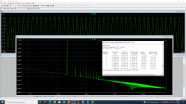
Would you share your circuit ?My simulation of this topology using PSU 63VDC. At low level output, 20kHz, 8 Ohm almost no distortion. I use OITPC compensation by Dadod.
The VAS current depends on the offset matching between the LSK489 and the LSJ689. This is a common behavior for full-complementary input stages. The shunt resistor across the collectors of the IPS current mirror stabilize it. Without those resistors the VAS current is theoretically undefined. The smaller those resistors, the better defined it is, but at some expense of IPS gain. The choice in the design is thus a compromise. The VAS bias current matters little, and a deviation during operation (e.g., warmup) from 12.0 to 12.7 mA is quite good. This issue is covered in the IPS/VAS chapter in my book.Hello Bob
Just finished building my version of the DH220C using the excellent LSK489B and LSJ689B for the IPS.
IPS current is set by a resistor placed between the emitters of the jfets.
I am not using a servo so there is a DC null cap in the NFB circuit.
VAS current is stabilized by 4k7 resistors shunting the collectors of the positive and negative mirrors.
The amplifier works and all currents and voltages are near simulated values with an average difference of 2%
Current on the IPS jfet emitters is very stable as well as current in the VAS buffers.
Simulated current in each VAS is 12mA but in my build it is never super stable.... It fluctuates between 12,7 and 12mA changing 0.1mA each second.
Increasing the shunt resistors (R58 and R59 in my build), does reduce THD but VAS current is even more unstable.
Is this behaviour normal ?
What should I do to completely stabilize VAS currents ?
Best
Ricardo Cruz
Cheers,
Bob
Thank you Bob.The VAS current depends on the offset matching between the LSK489 and the LSJ689. This is a common behavior for full-complementary input stages. The shunt resistor across the collectors of the IPS current mirror stabilize it. Without those resistors the VAS current is theoretically undefined. The smaller those resistors, the better defined it is, but at some expense of IPS gain. The choice in the design is thus a compromise. The VAS bias current matters little, and a deviation during operation (e.g., warmup) from 12.0 to 12.7 mA is quite good. This issue is covered in the IPS/VAS chapter in my book.
Cheers,
Bob
It does sound very good indeed
Sorry. I design it for a friend.Would you share your circuit ?
Other solution is you can add common mode control loop in HEC IPS (other amplifier of Bob Cordell) instead of resistor in current mirror's collectors.
Now I try to sim my idea.
Maybe you could show the clipping behaviour?My simulation of this topology using PSU 63VDC. At low level output, 20kHz, 8 Ohm almost no distortion. I use OITPC compensation by Dadod.
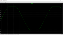
Nice clean high-frequency clipping - that's what I like.Clipping at 20 kHz 8 Ohm.
Cheers,
Bob
This is my 100W CFA OITPC (OPS serial combination of ClassA and ClassB) clipping, simulated and real amp clipping.Nice clean high-frequency clipping - that's what I like.
Cheers,
Bob
Damir
Attachments
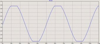
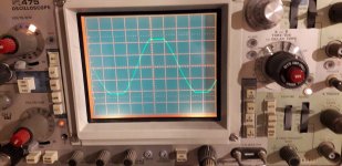
Very nice DamirThis is my 100W CFA OITPC (OPS serial combination of ClassA and ClassB) clipping, simulated and real amp clipping.
Damir
Happy new year.
Stein
Happy New Year to you Stein.Very nice Damir
Happy new year.
Stein
- Home
- Amplifiers
- Solid State
- Bob Cordell Interview: BJT vs. MOSFET