If the heatsink is barely warm then you have no problem with excess bias current. That doesn't mean there isn't some intermittent problem lurking though.
Now the bad news") the bias current setting has no real effect on the operation of the earlier transistors. Whether the bias is set for zero, 100ma or a couple of amps, the earlier stages are running just the same for each setting. All that varies is the voltage across the trimmer potentiometer. You will find there is around 700 to 800mv across that trimmer in normal operation (bias at 100ma) and perhaps as much (much being a relative term) as 1.5 to 2 volts for bias currents of a few hundred milliamps. That is the only parameter that changes. The currents in the 100 ohms and the little transistors stays the same.
the bias current setting has no real effect on the operation of the earlier transistors. Whether the bias is set for zero, 100ma or a couple of amps, the earlier stages are running just the same for each setting. All that varies is the voltage across the trimmer potentiometer. You will find there is around 700 to 800mv across that trimmer in normal operation (bias at 100ma) and perhaps as much (much being a relative term) as 1.5 to 2 volts for bias currents of a few hundred milliamps. That is the only parameter that changes. The currents in the 100 ohms and the little transistors stays the same.
Bottom line is the trimmer setting has no effect on anything other than the output stage current.
Now the bad news
the bias current setting has no real effect on the operation of the earlier transistors. Whether the bias is set for zero, 100ma or a couple of amps, the earlier stages are running just the same for each setting. All that varies is the voltage across the trimmer potentiometer. You will find there is around 700 to 800mv across that trimmer in normal operation (bias at 100ma) and perhaps as much (much being a relative term) as 1.5 to 2 volts for bias currents of a few hundred milliamps. That is the only parameter that changes. The currents in the 100 ohms and the little transistors stays the same.Bottom line is the trimmer setting has no effect on anything other than the output stage current.
I scratched the top and there was some dry stuff there. I don't know if it had leaked out or was just something sticky that had come off a finger or something at some point. I've got replacements on order so will be replacing all the small transistors.
It must be OK for the amp to play...
Pictures are deceiving sometimes. It looked a little as though it could have cracked and split, but obviously not the case as it is working.
It must be OK for the amp to play...
Pictures are deceiving sometimes. It looked a little as though it could have cracked and split, but obviously not the case as it is working.
As you said in the last post, there might be some intermittent fault, so I'll replace everything just to be sure.
I'm wondering how to check if the bias current is sufficient. From listening, I can tell if it's too low, as there is some higher frequency noise, which I assume is from uneven switching between the negative and positive halves of the wave, and I can turn it up until that goes away.
I might borrow an oscilloscope from work and look at the output directly playing some test tones, and see if I can record it and check when it looks like a proper sine wave.
You will find in practice that any current over a couple of millamps (as low as that) reduces any audible distortion to essentially inaudible.
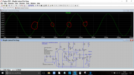
An oscilloscope will probably show the distortion but as above, once you go over a couple of milliamps it will vanish. This shows a simulation of the old Maplin lateral FET amp at zero bias current and that really is all you would see. This is at 10kHz with a 4 ohm load.
A clean 1kHz sine test tone played at very very low volume is good for hearing crossover distortion.
Attachments
If the heatsink is barely warm then you have no problem with excess bias current. That doesn't mean there isn't some intermittent problem lurking though.
Now the bad news
Bottom line is the trimmer setting has no effect on anything other than the output stage current.
Oh well. This is oriented so that this end of the circuit is vertically below the rest of the amp, so it should be cooler, but it is in a boxed enclosure in the back of the sub with just the heatsink sticking out, and 2 mm clearance around for air to flow in and up, so it might have got hot just from the ambient temperature in the box getting too hot.
This failure did follow my amp suffering some issues with the digital stage crackling due to diodes failing discussed here, so I don't know if it could be that the amp might have output some nasty signals during that episode.
Hard to say. If the amp worked OK after the diode episode then its kind of unlikely to be related.
If the amp actually failed while the diode problem was causing nasty spikes then yes, I guess its possible. In that case perhaps the amp 'latched' in some way with the output driven hard to a rail and the feedback unable to correct a massive overdrive situation.
If the amp actually failed while the diode problem was causing nasty spikes then yes, I guess its possible. In that case perhaps the amp 'latched' in some way with the output driven hard to a rail and the feedback unable to correct a massive overdrive situation.
You will find in practice that any current over a couple of millamps (as low as that) reduces any audible distortion to essentially inaudible.
An oscilloscope will probably show the distortion but as above, once you go over a couple of milliamps it will vanish. This shows a simulation of the old Maplin lateral FET amp at zero bias current and that really is all you would see. This is at 10kHz with a 4 ohm load.
A clean 1kHz sine test tone played at very very low volume is good for hearing crossover distortion.
I am going to have to get into modelling circuits, it's the next step for me after I finish building my daughter a chip amp and speakers.
I've had the sub on for about 4 hours now, not doing too much but just playing low level, and it is still not hotter than baby milk. Very different from how it was.
I'll try something with more bass at the weekend and see how it sounds in anger!
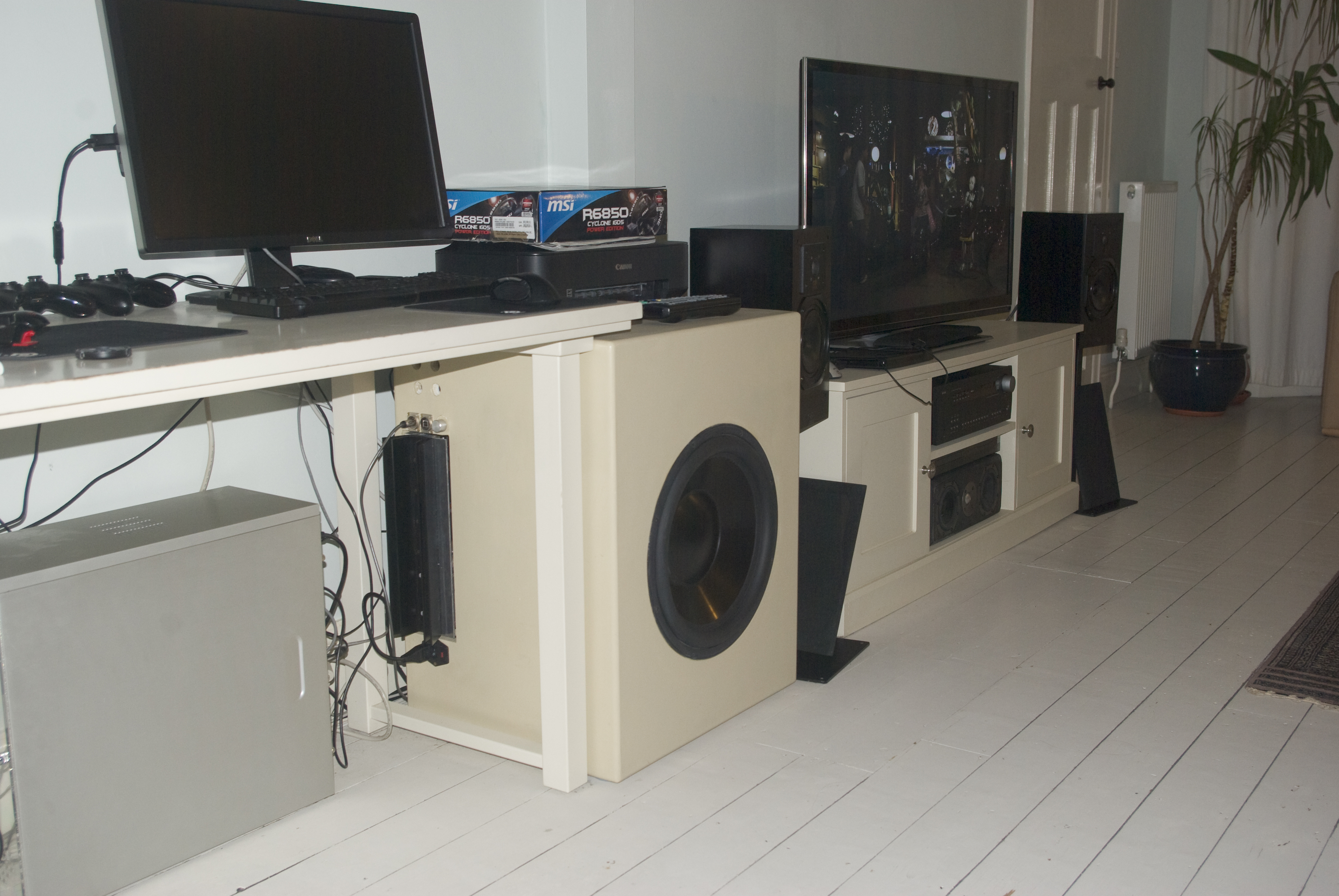
Here it is, back in the box.
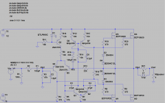
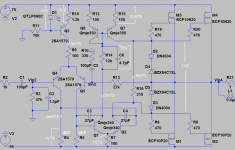
Right, I've made a model for this circuit, but realised that I have no idea of the values for the LED, or the Zener diodes, or the resistor inside the inductor on the output. I can't read them at all. I also could not find the 2SA1016 transistors, so I built it with 2SA1579's. Is there a better alternative, or does anyone have the model files?
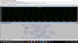
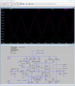
Here's the model from LTSpice XVII, which I think is working, and may I thank Mooly for the excellent guides on how to get going on this!
P.S. I had to rename the .lib files to .txt to upload, please rename back to use.
Here's the model from LTSpice XVII, which I think is working, and may I thank Mooly for the excellent guides on how to get going on this!
P.S. I had to rename the .lib files to .txt to upload, please rename back to use.
Attachments
That's great, well done 
I used some of Bob Cordells and Ian Heggluns models.
For the small signal transistors you will find that it doesn't really make much difference what you use in a circuit like this as it is not particularly critical.
I used some of Bob Cordells and Ian Heggluns models.
For the small signal transistors you will find that it doesn't really make much difference what you use in a circuit like this as it is not particularly critical.
Attachments
That's one for DrNick I'm not familiar with the amp although just changing those to 4k7 in my simulation and the output latches to the positive rail.
Now flying in the face of what I said above... altering the spec of the MJE340's will get it to run with those values. So if they really are 4k7 I would say there is something very marginal about the design in that area.
I'm not familiar with the amp although just changing those to 4k7 in my simulation and the output latches to the positive rail.Now flying in the face of what I said above... altering the spec of the MJE340's will get it to run with those values. So if they really are 4k7 I would say there is something very marginal about the design in that area.
R4 and R5 not 47k , it's 4.7k !
Mona
Yup, that's me not able to read my own handwriting at 3 am. As I am such a total beginner I wrote down the colours when I was originally tracing the circuit and it is definitely yellow violet red brown, and the original Hitachi scheme had 3.9k so it's probably the blueprint value.
Thanks!
That's one for DrNick
Now flying in the face of what I said above... altering the spec of the MJE340's will get it to run with those values. So if they really are 4k7 I would say there is something very marginal about the design in that area.
I've got the models for the ECF10N20 and 10P20 as I could not find the 10N16 and 10P16 (which are what I've actually got on the board) from http://www.diyaudio.com/forums/solid-state/4094-lateral-mosfet-replacements-2sk1058-hitachi-2.html#post171238
I got the model for the 340 and 350 from Simulation Models: MJE340 and Simulation Models: MJE350
The 2SA1579 is a built in model, and I chode the zener diode and LED pretty much at random, so I have no idea if they are good choices or not.
I've attached the corrected model, and it seems to run okay
Attachments
Yes, the colour of the LED is the deciding factor (really ). I guessed it would be a red one.
If you measure the actual volt drop across the diode in the real amp then you can replace D1 in the simulation with a voltage source set to the same measured voltage.
Bob Cordells LTpsice models have become something of a standard and for the lateral FET's I like Ian Heggluns models.
http://www.diyaudio.com/forums/soft...-power-mosfet-models-ltspice.html#post4365741
). I guessed it would be a red one.If you measure the actual volt drop across the diode in the real amp then you can replace D1 in the simulation with a voltage source set to the same measured voltage.
Bob Cordells LTpsice models have become something of a standard and for the lateral FET's I like Ian Heggluns models.
http://www.diyaudio.com/forums/soft...-power-mosfet-models-ltspice.html#post4365741
Yes, the colour of the LED is the deciding factor (really
Sorry, should have said. It's green, so maybe anywhere from 2 to 4 V. I wish I'd measured the drop across R11 more accurately, as if the positive rail is 75 V (I think is was within 10 mV), I could have just subtracted R11 from that. I measured either 71 or 70, but didn't bother with more than 2 sf.
Yes, the colour of the LED is the deciding factor (really
If you measure the actual volt drop across the diode in the real amp then you can replace D1 in the simulation with a voltage source set to the same measured voltage.
Bob Cordells LTpsice models have become something of a standard and for the lateral FET's I like Ian Heggluns models.
http://www.diyaudio.com/forums/soft...-power-mosfet-models-ltspice.html#post4365741
Great, I've used these for the latest version, and it makes the +ve and -ve rails pretty symmetrical, which they were not before.
I've got a generic LED model from http://www.diyaudio.com/forums/software-tools/25884-spice-models-led.html#post301141 and modded it until the voltages fit as closely as possible by setting N=3.95.
This model now shows the bias giving 100 mA or so from each Mosfet, so I guess that's double the 100 mA per pair guideline. Seeing as this is so sensitive to the LED voltage, I'll measure that this weekend.
Thanks again for all the help, I really feel I'm learning some useful stuff here.
Attachments
You're very welcome
I'm still puzzled over those 4k7 resistors and Bobs MJE340 model which will not give a working amplifier. However if I increase R7 from 100 to just 102 ohms then it all runs correctly.
Something is very marginal there.
I have been using 2SA1579's for the first pair, and with these it does not seem so on-edge as with the 2N5401C's. I only chose the 2SA1579's as I could not find a model for the original 2SA1016's and they have the same Vceo parameter, but is it possible there is some other significant difference between the 2SA1579 and 2N5401C's?
I realised I had used Bob's model for the Mosfets, but not the MJE340's and MJE 350's, so I updated that and with the modified LED it fits okay to the voltages I had measured.
Attachments
With anything like this, and whether I was either designing this from scratch or looking for problems with a built up version, I would look at testing for real by altering those resistors by perhaps 50% each way and see if the design would still function correctly.
Sometimes setting values empirically can be a very useful tool. No part should be super critical in what is a fairly generic type of circuit.
Raising the 100 ohm a couple of percent makes the simulation work. Raising the 4k7 to 5k1 also does the same. So in this case I would really like to see on the real amp whether for example a 3k9 would be OK. If it wasn't, then the design imo would need altering to make it less critical.
- Status
- This old topic is closed. If you want to reopen this topic, contact a moderator using the "Report Post" button.
- Home
- Amplifiers
- Solid State
- Blown resistors in a BK Electronics MF300? With circuit diagram!