My BK Electronics MF300 mono amp in my subwoofer has started giving -75V at the output terminals. Nothing damaged, just obviously not working. I built the subwoofer four years ago following much help from these pages, so I've come back.
I think I know what has gone wrong and I think I've worked out what the circuit is, I'm just posting to see if anyone who knows what they are doing can see a problem with what I think I've found, and to ask how to set the bias up properly once I've fixed it. I wiggled the variable resistor around to see if it had any effect, and didn't mark where it was to start.
The top view of the input section is here
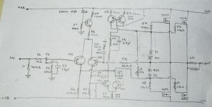
The schematic is something like this, as best as I can make it out.
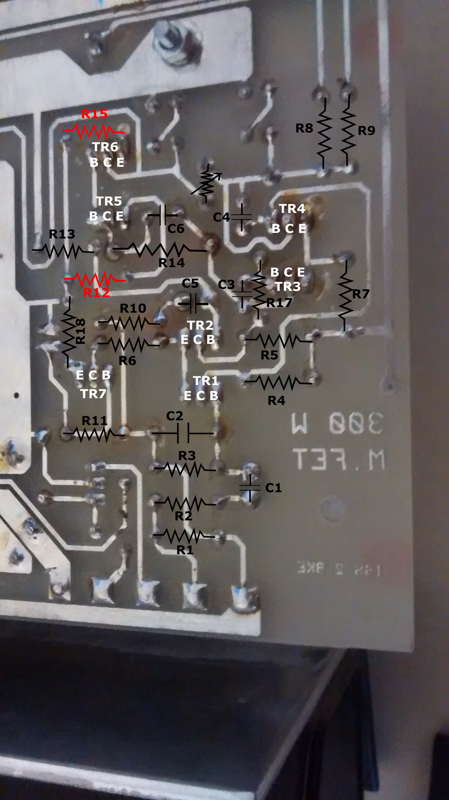
The reverse view, flipped so the bits are in the same place as in the top view is
When I turn it on, the positive and negative rails go to +/- 75 V, and I measure 150 V across R15 and R12. They are both 100 Ohm, so I think they have died and there is no connection there.
So, three questions:
1. How do I tell if the transistors have also died, I don't know what voltages to expect at the legs.
2. Can I just replace the resistors with more 100 Ohm ones, is it worth getting higher power ones. I don't know what rating the existing ones had.
3. If I get it working again, how do I adjust the bias. Where should I measure to check this?
Thanks!
I should add, the schematic seems to be close to the original Hitachi lateral mosfet design discussed here but not quite the same. It has a lot of similarities with Rod Elliot's design detailed here.
I think I know what has gone wrong and I think I've worked out what the circuit is, I'm just posting to see if anyone who knows what they are doing can see a problem with what I think I've found, and to ask how to set the bias up properly once I've fixed it. I wiggled the variable resistor around to see if it had any effect, and didn't mark where it was to start.
The top view of the input section is here
An externally hosted image should be here but it was not working when we last tested it.
The schematic is something like this, as best as I can make it out.
An externally hosted image should be here but it was not working when we last tested it.
The reverse view, flipped so the bits are in the same place as in the top view is
An externally hosted image should be here but it was not working when we last tested it.
When I turn it on, the positive and negative rails go to +/- 75 V, and I measure 150 V across R15 and R12. They are both 100 Ohm, so I think they have died and there is no connection there.
So, three questions:
1. How do I tell if the transistors have also died, I don't know what voltages to expect at the legs.
2. Can I just replace the resistors with more 100 Ohm ones, is it worth getting higher power ones. I don't know what rating the existing ones had.
3. If I get it working again, how do I adjust the bias. Where should I measure to check this?
Thanks!
I should add, the schematic seems to be close to the original Hitachi lateral mosfet design discussed here but not quite the same. It has a lot of similarities with Rod Elliot's design detailed here.
Last edited:
If the MOSFETs have failed they will have failed short source to drain. AS you are getting a -ve voltage out then it would be the lower half. These MOSFETs are quite rugged though so it is unlikely.
What I think is more likely is that the amp has been driven into clipping, turned on the gate protection zeners, and this has blown the resistors you mention. It's possible they are fusible resistors, intended to fail open circuit when there is too much current.
For setting bias current, normally you would monitor voltage drop across an emitter resistor - but this amp has none (ugh). Next best thing is to stick an ammeter in the supply leads and adjust that way.
Personally.... I don't think much of the circuit, and would take those lateral MOSFETs and build something better around them.
Thanks for the reply!
If it is reasonable that this could just be those resistors, I'll just try replacing them. Is the value critical, or is matching the resistors important? With these having failed is there any reason that a higher or lower value would be better, or would changing the values of these cause other problems?
This normally drives a 15" Dayton subwoofer, which just retracts about 1" if you turn the power on. I've only tried that for half a second at a time.
Just replace them. Normal 1% metal film resistors should be just fine without matching.
Ugh, its really not a good idea to run ANY DC through a voice coil. Check the speaker itself by pushing the cone gently around the center magnet area. If the movement is not smooth and you feel grating, the coil has fried :/
Ugh, its really not a good idea to run ANY DC through a voice coil. Check the speaker itself by pushing the cone gently around the center magnet area. If the movement is not smooth and you feel grating, the coil has fried :/
As I see it, the most probable cause is a short between c-b of the transistor with R15 at the emitter.Takes out the two resistors and is bad for D1 and ZD1 but perhaps they survive.
The schematic has two errors, D1 and R11 are wrong.
Mona
Yes, R11 goes to earth after the LED, sorry, and D1 is the wrong way round. The base of TR7 comes straight off the LED. Thanks very much for looking at this!
Best Wishes,
Nick.
So, after replacing the 100 Ohm resistors it is working again, much as before, but the heatsink got quite hot after 5 minutes, hotter then I remember. As I had messed with the bias on the variable resistor I thought it best to turn it off until I worked out which way to change it to lower the temperature. When I put it back together I set the resistor to half way - 500 Ohms - just to see if it was going to work.
Would increasing the resistance be the way to lower the bias current and hence the temperature?
Thanks all,
Nick.
Would increasing the resistance be the way to lower the bias current and hence the temperature?
Thanks all,
Nick.
Thanks! I had searched online, but could not find anything. I measured the voltage across R15 once the new resistor was in and it was about 700 mV, R12 was about the same. The transistors are MJE 340 and 350 transistors. I only managed to read the text today. If I measure the voltages at the legs when it's on would that confirm if they are working normally?
Best Wishes,
Nick.
Best Wishes,
Nick.
Your getting some great advice here
I know, I only built this subwoofer after asking a load of questions on the subwoofer forum about four years back, and getting a lot of help. This place is a gold mine.
other than to suggest replacing all four of those small transistors, the upper and lower pair.
Yup, I think I might just do that, I'll have to order online though, but it should not take too long.
Is R7 OK ?
R7 had 100 mV across it before replacing the broken ones, I'll check again tomorrow to see if it's different now.
Thanks!
Nick.
It's the opposite, increasing gives more bias current!
Great, I was trying to find out online, but it's good to hear it from someone who has looked at this circuit to be sure.
Better first find out why those resistors have burned.Still think there's something wrong with the transistor at R15.
Mona
It's £4 for a pair of MJE340's and a pair of MJE350's so I've ordered them and will replace them just to be safe. Might as well while I'm sorting it out.
Thanks!
Nick.
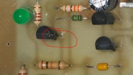
Has that transistor I circled gone pop. Pictures can be misleading I know but it looks suspect as shown.
I'll get the amp out tomorrow and have a closer look. It's £4 for 4 of these so have ordered these too. Looks like I'll replace all the small transistors, just to be safe.
Thanks!
Nick.
I have tried adjusting the bias resistor today, and recorded the voltages across the resistors while playing a 50 Hz sine wave at a low volume, with 5 mV then 23 mV (not sure if RMS) as the input signal.
As it was apparently working, this is with the speaker attached. I know I should be worried about it not working, but it seems to be playing, and I did not have suitable load otherwise. It is a Dayton 390 HF so nominally 4 Ohms.
The voltages recorded for the 23 mV input were
R1 0
R2 0
R3 90 mV
R4 2.22 V
R5 2.24 V
R6 118 mV
R7 1.6 V
R8 0
R9 0
R10 5 mV
R11 70 mV
R12 800 mV
R13 40 mV DC 395 mV AC
R14 90 V
R15 813 mV
R16 (set at 210 Ohms) 1.4 V
R19 0
R20 0
I tried altering the bias while listening to the 50 Hz signal. At close to zero on the variable resistor R16 there were audible high frequency buzzing sounds, so I'm guessing a very bad class B setting. I turned it up until I could not hear any further improvement then stopped. It is much cooler now than before.
I'm waiting for the replacement devices, so will change the semis in due course.
The standard bias current for laterals in Class AB is 100ma per pair. In practice you can go well below that before anything audible shows up but the problem is that at very low currents the bias point will be very variable with regard to temperature.
Looking at the photo and there doesn't seem to be an easy way to set the bias. What I would do is carefully unsolder the 'drain' from one of the four devices and then carefully tag a 1 ohm across the now open points i.e. drain to PCB. Then nonitor the voltage across the one ohm and adjust for around 100 millivolts which would correspond to 0.1 amps for that pair.
Looking at the photo and there doesn't seem to be an easy way to set the bias. What I would do is carefully unsolder the 'drain' from one of the four devices and then carefully tag a 1 ohm across the now open points i.e. drain to PCB. Then nonitor the voltage across the one ohm and adjust for around 100 millivolts which would correspond to 0.1 amps for that pair.
So after an hour of playing music at normal levels (not loud - maybe 1 W through the main stereo speakers) the heatsink is barely warm. It used to be really hot - just touchable. The resistors that failed lasted 4 years. Maybe this unit was set up running too much bias and just cooked them?
Has that transistor I circled gone pop. Pictures can be misleading I know but it looks suspect as shown.
I scratched the top and there was some dry stuff there. I don't know if it had leaked out or was just something sticky that had come off a finger or something at some point. I've got replacements on order so will be replacing all the small transistors.
- Status
- This old topic is closed. If you want to reopen this topic, contact a moderator using the "Report Post" button.
- Home
- Amplifiers
- Solid State
- Blown resistors in a BK Electronics MF300? With circuit diagram!