it is a very good amplifier
Giaime
Seeing that Q42 and Q44 have vwery slightly more current available from the current mirror than the loaded side, I would have thought that R77 should have been on the opposite side ?
Seeing that the voltages are so close already, that may be all you need with this particular circuit. I have only tried very well matched differential transistors in more conventional circuits, with, and without current mirrors, so I am only guessing here.
SandyK
Carlos
"But this time, with the same speaker and almost the same parts (supply is different....hummm) i had a very good results."
Is this just "one speaker"?
therefore also one amp module?
If the bass was week or the highs hurt i would measure the module to see why, rather than just dismiss the whole topology.
that is, unless i had calibrated eardrum(s)
allan
Re: it is a very good amplifier
Hello SandyK!
Look at the voltages in my last post: Q41 and Q42 have the same Vce, minus a mere 1mV difference Of course that's SPICE only, but if you cannot make those two Vce equal, with perfectly equal bjts (as in SPICE), that won't be easy to make them equal in reality, with different transistors...
EDIT: I saw your last post after posting mine. Yes, the resistor goes there, because in this design the voltage difference between the collectors is in opposite sign of what you were suggesting me. Maybe, as you say, it's a current mirror trick.
I cannot hear this amp's soundstage, it's still only on SPICE. Maybe I'll build it in the future, it looks promising.
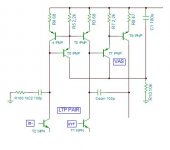
Attached, the full schematic:
Hello SandyK!
sandyK said:I would say Q41 and Q42 initially.Try and get difference between their collectors closer by a resistor from the unloaded side of the differential pair collector to -VE rail, which gives equivalent to the loading of the BC547. (try something like 22Megohms to see if it makes an audible improvement, and take it from there) I would imagine that you already have a better than average sound stage if those pairs of transistors are well matched .
SandyK
Look at the voltages in my last post: Q41 and Q42 have the same Vce, minus a mere 1mV difference
Of course that's SPICE only, but if you cannot make those two Vce equal, with perfectly equal bjts (as in SPICE), that won't be easy to make them equal in reality, with different transistors...EDIT: I saw your last post after posting mine. Yes, the resistor goes there, because in this design the voltage difference between the collectors is in opposite sign of what you were suggesting me. Maybe, as you say, it's a current mirror trick.
I cannot hear this amp's soundstage, it's still only on SPICE. Maybe I'll build it in the future, it looks promising.
Attached, the full schematic:
Attachments
it is a very good amplifier
Giaime
Don't forget that the unloaded side still has slightly more current, due to the very small bias current on the loaded side, reducing available current to the input side's transistors. This will most likely be more evident in the real world. Try moving that resistor.
Regards
SandyK
Giaime
Don't forget that the unloaded side still has slightly more current, due to the very small bias current on the loaded side, reducing available current to the input side's transistors. This will most likely be more evident in the real world. Try moving that resistor.
Regards
SandyK
I just pointed out that many of his schematics on the net are plainly wrong
From the moment I opened his book it was obvious he would have been better served by a better publisher and editor. Even when the figures are correct, the are often blurry. Of course I don't know the economic circumstances so maybe he did the best he could. Maybe some of this is because the book is really a bunch of individual articles strung together.
I was once pressed in to service to edit a couple of technical publications even though I understood zilch about TWTs and kystrons. I also had never done any editing before. Yet the result was much clearing than what Self's publisher had wrought.
it is a very good amplifier
I have the same edition as Andrew and haven't noticed any glaring errors. The diagrams are clear too.
I believe that a few of the "errors" mentioned were cleared up in another thread that Sam was involved in.
Andrew do you find the 3rd edition hard to read due to print quality ?
Regards
SandyK
I have the same edition as Andrew and haven't noticed any glaring errors. The diagrams are clear too.
I believe that a few of the "errors" mentioned were cleared up in another thread that Sam was involved in.
Andrew do you find the 3rd edition hard to read due to print quality ?
Regards
SandyK
I was thinking perhaps of figures 5.6, 6.16 and 7.5. Some component names and and vales are not readable. The line thickness is to gread so the merge together. It's always possible I have a bad printing.
As long as I'm justifying my complaints, I would have liked a more extensive index. Sometimes I find myself thinking; "I know it's in here somewhere" but it cvan be a chore to find the exact point I'm looking for.
This is not a complaint directed at Self, these should be addressed by the publisher.
As long as I'm justifying my complaints, I would have liked a more extensive index. Sometimes I find myself thinking; "I know it's in here somewhere" but it cvan be a chore to find the exact point I'm looking for.
This is not a complaint directed at Self, these should be addressed by the publisher.
Re: Re: ....it is a very good amplifier
What i said about the usefulness of current mirror it is not only on paper. I have the bad habit to implement in practice what i draw on the paper. After the implementation of circuit i pass the sample from some hard tests in the workbench by injecting square waves of different frequencies in his input with a dummy load in his output and i observe with the scope. I use sinus waves only for the finding of clipping level. If all goes well, then i make audition tests ( as my friend SandyK ) with some other persons. I am in possition to confirm you that what i have seen in the scope it is translated exactly in the quality of music reproduced from the amplifier sample. And the quality of sound it is great. The only improvement that i succedded, according the advice of SandyK, was a further improvement in high frequencies by changing the Miller compensation capacitor from ceramic type in silvered mica. From the D.Self propotitions i am using only the E.F. arrangement instead cascode in VAS stage. What is the beneffit of using CCS in all stages, it is that in practice we can to build bigger and bigger and bigger power amplifiers simply by increasing the voltage and the power level of P.S. changing transistors with higher Vce and multiplying the number of output transistors, with exactly the same circuit each time. Such type amplifiers builded enough years before the edition of D.Self book. And me also i suppose a litle mysterious the CCS arrangement according to D.Self and i reject it. Also i consider that the removing of b-e resistors of the output transistors and its replacing from the shared emiter resistor between the output drivers it is mistake because the output then becames some unstable. These resistors provide local feedback in output transistors and may stay in place in conjuction with the shared resistor. Thus the profit it is doubled.
Fotios
Dear neighbor GiaimeGiaime said:Hello fotios,
I absolutely agree, on paper it's a great thing. I was asking myself if it gives too much instability problems, that's why (I thought) people says it's worse sounding. Or maybe they forgot to use high beta devices, and match them
What i said about the usefulness of current mirror it is not only on paper. I have the bad habit to implement in practice what i draw on the paper. After the implementation of circuit i pass the sample from some hard tests in the workbench by injecting square waves of different frequencies in his input with a dummy load in his output and i observe with the scope. I use sinus waves only for the finding of clipping level. If all goes well, then i make audition tests ( as my friend SandyK ) with some other persons. I am in possition to confirm you that what i have seen in the scope it is translated exactly in the quality of music reproduced from the amplifier sample. And the quality of sound it is great. The only improvement that i succedded, according the advice of SandyK, was a further improvement in high frequencies by changing the Miller compensation capacitor from ceramic type in silvered mica. From the D.Self propotitions i am using only the E.F. arrangement instead cascode in VAS stage. What is the beneffit of using CCS in all stages, it is that in practice we can to build bigger and bigger and bigger power amplifiers simply by increasing the voltage and the power level of P.S. changing transistors with higher Vce and multiplying the number of output transistors, with exactly the same circuit each time. Such type amplifiers builded enough years before the edition of D.Self book. And me also i suppose a litle mysterious the CCS arrangement according to D.Self and i reject it. Also i consider that the removing of b-e resistors of the output transistors and its replacing from the shared emiter resistor between the output drivers it is mistake because the output then becames some unstable. These resistors provide local feedback in output transistors and may stay in place in conjuction with the shared resistor. Thus the profit it is doubled.
Fotios
Hi Fotios (and all),
what you say is perfectly mirroredD ) in my little experience with those "evolute" circuits. I often go blindly for thd reduction in SPICE because doing this I never worsened the sound of an amp.
(about D.Self errors, I was talking mainly to his website! In fact my design started as a copy of the first schematic you can find here , that cannot work as drawn )
)
what you say is perfectly mirrored
D ) in my little experience with those "evolute" circuits. I often go blindly for thd reduction in SPICE because doing this I never worsened the sound of an amp.(about D.Self errors, I was talking mainly to his website! In fact my design started as a copy of the first schematic you can find here , that cannot work as drawn
)do you mean Fig1a or Fig33?
Self tells us that changing R2 in fig1a should be done.
As shown the LTP is pulling 4times the current through TR3 cf. TR2.
But, Self is using fig 1a to discuss the DESIGN of an amplifier and does not suggest building it.
As far as I can tell fig33 works.
Self tells us that changing R2 in fig1a should be done.
As shown the LTP is pulling 4times the current through TR3 cf. TR2.
But, Self is using fig 1a to discuss the DESIGN of an amplifier and does not suggest building it.
As far as I can tell fig33 works.
AndrewT said:do you mean Fig1a or Fig33?
Self tells us that changing R2 in fig1a should be done.
As shown the LTP is pulling 4times the current through TR3 cf. TR2.
But, Self is using fig 1a to discuss the DESIGN of an amplifier and does not suggest building it.
As far as I can tell fig33 works.
Yes you're perfectly right. I was referring to fig 1a, that I used as a basic template to design my amp.
It's true, someone so ... to build the amp without reading the article actually deserves such a bad surprise
Hi Giaime,
I think C12 in your schematics shoud be connected to the negative power supply rail, in parallel with Zener D9, not to ground. I have seen some schematics doing so and then adding a small cap (10 nf) to ground. Fearing every trace of instabilty, I also think it is a good idea to include a base stopper in series with the Q30 base, it may help for fast recovery after saturation.
To enhance power supply rejection of the CCS's, Self also suggests the decoupling of your R65 in two 10 kOhm with an electrolytic (47 µ) connected to the positive power supply rail.
AndrewT said:do you mean Fig1a or Fig33?
Self tells us that changing R2 in fig1a should be done.
As shown the LTP is pulling 4times the current through TR3 cf. TR2.
But, Self is using fig 1a to discuss the DESIGN of an amplifier and does not suggest building it.
As far as I can tell fig33 works.
If you are addressed to me, i mean in fig33 that the eliminating of the b-e resistors (12R to 22R usually) in output pair TR7-TR9 IMHO it is wrong. Because they offer a local feedback in output transistors, thus greater stability, and from the other hand they don't affect the benefit offered by the shared emitter resistor R15. You may be right that this arrangement as presented in fig33 it works without doubt. But we must take into account that the output devices are only two! I am wondering which of us includes only one pair in output? No one of the drawings of D.Self, from as much as i know, includes multiple pairs in output. Maybe mr. Self must be experimented with a such case and maybe he is revised his propositions; because a test for one or two hours it does not says nothing compared with the usual test of 24 hours (like my beloved car race of LeMans24h) in which put great companies their power amplifier samples. The quality of sound in all modern designs IMHO vary between 9,5 to 9,9 in a graduation of 10. And this because the excellent type of parts (from transistors to capacitors) offered today in the market. The rest 9,9-9,5=0,4 it is a curious race between designers and constructors. And the cost to the consumer it is of astronomical size many times! I am thinking some times, people don't know a better way to spend money? Where they hidden their money and all the time cry: I haven't moneys, i am penniless, i am in bad economic situation, i haven't the possibility to settle my debts! And the next day, we are seeing in his living room a very expensive pair of monoblock amplifier and a new pair of exotic speakers!!! I am tired more from these people.
Sorry for my explosion Andrew and each one other.
As say Plato great ideas only from modesty in thought people (i hope the translation is comprehensible, i am learning further English from the conversation with you, i request your comprehension to this).
To not misunderstand me and you consider me as feigned patriotist, may to remind in mr D.Self and to you the Uncertainity principle of the famous Deutch Werner Heisenberg (in which based the most known to us the audio freaks, the named Johnson noise or Nyquist noise or thermal noise, because the second thermodynamics principle or ENTROPY actually it says the same with Heisenberg's principle); also my beloved contemporary physicist Steven Hawking which rejected in practice Einstein's statement "God don't throw dices" by saying the opposite based on the Heisenberg's basic principle of quantum mechanics that this principle is applicable not only in microcosm but also in infinity things such as the universe (i think for this reason he don't take yet a nobel for his work). For my big surprise, in the book of the well known existentialist Albert Camus "The Fall" i have read a similar expression, that: "In all of my life the unique God which i have meet it is the LUCK!".
What can say anyone from us "the audio freaks" against all these statements, theories, principles etc? What can say to me mr D.Self or mr_ and mr_ and mr_............? Enough misters!
The people in Africa starves and feel dry due to underdeveloped caused mainly from religion prejudices, the same in many countries of Far East, our planet, OUR HOME (forget the borders) it is faced with surviving problems NOT AFTER 50 YEARS but after 2 to 3 years as i understand with my humble thought.
I escaped from our theme. I ask your forgiveness. It is Sunday.
A little and indisposed servant of this earth
Fotios
Here are are suggestions I had in mind since long ago about the Self's amp. Sorry, I draw the other polarity than used by Self.
Self suggests, but does not apply to his published circuits, that the power supply injection can be lowered by decoupling the collector of the beta enhancement transistor of the VAS. So let's decouple it.
An additionnal emitter follower transistor can somewhat equalize the current in the mirror and probably make it more linear. This is used by Bob Cordell's amplifier published in a Siliconix application note in a VAS is à la Hitachi. It collector is of course also decoupled.
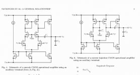
Another scheme rather than a cascode for Cdom not altering the PSSR has been suggested in another thread but I could not find it. I hope I am right in drawing it here : a capacitor of same value as Cdom is connected in series with a resistor (which value ?) between ground and the second branch of the mirror.
At last, but not drawn here, I thought of a mix of Cherry's compensation (Cdom connected to the power output rather than to the VAS output) and Self way to enhance the openloop bandwidth by local feedback with a simple resistor connected across the Vas. I thought of a resistor (mabe in series with a cap) connected to the power output and the emitter of a common base transistor in the input stage, the cascode described by Lumanauw above for a way to connect Cdom being back.
Self suggests, but does not apply to his published circuits, that the power supply injection can be lowered by decoupling the collector of the beta enhancement transistor of the VAS. So let's decouple it.
An additionnal emitter follower transistor can somewhat equalize the current in the mirror and probably make it more linear. This is used by Bob Cordell's amplifier published in a Siliconix application note in a VAS is à la Hitachi. It collector is of course also decoupled.
Another scheme rather than a cascode for Cdom not altering the PSSR has been suggested in another thread but I could not find it. I hope I am right in drawing it here : a capacitor of same value as Cdom is connected in series with a resistor (which value ?) between ground and the second branch of the mirror.
At last, but not drawn here, I thought of a mix of Cherry's compensation (Cdom connected to the power output rather than to the VAS output) and Self way to enhance the openloop bandwidth by local feedback with a simple resistor connected across the Vas. I thought of a resistor (mabe in series with a cap) connected to the power output and the emitter of a common base transistor in the input stage, the cascode described by Lumanauw above for a way to connect Cdom being back.
Attachments
Hi, Forr,
It's possible. But the frequency is a bit too low for RF filtering. R=11k, C=180pF. The lowpass is at 80.3khz. The feedback system cannot sense anything happening at the output node above 80.3khz, so, the feedback system cannot fix anything above 80.3khz.
Maybe it is there from stabilization needs?
It's possible. But the frequency is a bit too low for RF filtering. R=11k, C=180pF. The lowpass is at 80.3khz. The feedback system cannot sense anything happening at the output node above 80.3khz, so, the feedback system cannot fix anything above 80.3khz.
Maybe it is there from stabilization needs?
Hi, Forr
Is this what you mean (the right pic)? Loading the other current mirror's leg with the same Cdom to make the current mirror has balanced load. It is also from Sackinger paper, he suggested 2 alternatives.Another scheme rather than a cascode for Cdom not altering the PSSR has been suggested in another thread but I could not find it. I hope I am right in drawing it here : a capacitor of same value as Cdom is connected in series with a resistor (which value ?) between ground and the second branch of the mirror.
Attachments
- Status
- This old topic is closed. If you want to reopen this topic, contact a moderator using the "Report Post" button.
- Home
- Amplifiers
- Solid State
- Blameless, Dx was wrong, it is a very good amplifier