Hi Ipanema,
this is going to be long so bear with me.
Simple way, buy a complex test set-up for many pounds and let the system measure it for you.
Manual method.
Insert an accurate adjustable attenuator before the amplifier.
Adjust the attenuator to ensure the input voltage of the test signal equals the output voltage at the frequency you start with (1kHz).
Adjust signal generator to next frequency and then adjust attenuator to match output to input voltage.
Record the frequency and gain, then repeat for the next frequency to cover the range of interest.
As you increase frequency the DMM will read wrongly, probably low due to drooping DMM response, but since you are comparing equal voltages that does not matter. My attenuator is about 140mm long and will have some capacitance and and inductance. This will curtail the high frequency accuracy but I have used it upto 150kHz and it is probably accurate to 50kHz. I cannot check this test instrument.
The attenuator I built has T pads switched in using 2pole change overs. It is 600ohm input and output impedance formed from selected 1% resistors and has db attenuator steps of 2 * 20db, 10db, 5db, 2*2db, 1db, 0.5db, 2*0.2db, 0.1db and 0.05db. This allows me to measure the gain of the amp to 0.1db accuracy at a resolution of about 0.02db from 0db to 60db. The T pads are easily built if you can find the website telling you how to do it (I did this about 8 years ago and don't have that kind of memory). I found all the smaller attenuation values easy to assemble accurately but the -20db Tpads need carefull and accurate selection to ensure the overall accuracy of the measurement. I have not found a way to measure below 10Hz accurately but I can estimate by reading off -0.1db, -0.2db, -0.5db and -1.0db, then comparing the rate of fall off to a butterworth filter response and then guessing the F3 bass frequency.
I will try to post the MSexcel spreadsheet tonight.
Ipanema said:Mod_evil,
Can't manage to post eagle file here. Can you send me your e-mail address?
thanks. [/B]
felnavarro@gmail.com
Thanks in Advance!
Ipanema ! Do you try to use a simple VAS instead darlington vas ?
I tried to not use degeneration resistor but I had to use a bigger compensate cap which make distortion still the same before improved . Can you understand me ?
Current amp still has thumb sound but its sound is quite "highest endest" , "live" , but treble sound seem to be "compression " . I can't still understand Carlos ' term
  .
.
I used a1011/c2344 for VAS in my sym amp before . I biased VAS with 20mA . Oh! I thought that I can understand "copression sound ". Then I replace them by d669/b649 but with 10mA . I have n't tried it with 20mA but I afraid of failure of d669/b649
. Perhaps using too many stage isn't a good thing .
Perhaps Lumanauw's friend feel right . What's wrong ?
I tried to not use degeneration resistor but I had to use a bigger compensate cap which make distortion still the same before improved . Can you understand me ?
Current amp still has thumb sound but its sound is quite "highest endest"
I used a1011/c2344 for VAS in my sym amp before . I biased VAS with 20mA . Oh! I thought that I can understand "copression sound ". Then I replace them by d669/b649 but with 10mA . I have n't tried it with 20mA but I afraid of failure of d669/b649
. Perhaps using too many stage isn't a good thing .
Perhaps Lumanauw's friend feel right . What's wrong ?
Hi Thanh,
at 1000mW a 20Cdeg/W heatsink (small) will have a temperature rise of 20 Cdeg above ambient.
To126 has a Rthc-s of 0.72Cdeg/W with paste only and 3Cdeg/W with mica & paste.
Using the mica resistance the Tc will be 3Cdeg above sink temp. For an ambient inside the amp of 30degC the Tc will be 30+20+3=53degC.
At 50Volts, soar is down to about 13W or 14W and derate a further 25% for Tc=53degC giving a MAXIMUM rating of 10W.
I suggest you use my previous figure of 5W and limit Iq to 20mA. This leaves a small margin for driving reactive loads. The drivers will need a much bigger margin just like the output transistors.
Now go and do your homework for other Iq values and then choose a suitable heatsink to suit your voltages and temperatures.
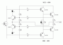
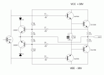
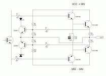
I am also about to build a blameless but I would like to add protection on output transistors. I think the following is correct. Should the protection transistor be connected as shown at bias transistor or at base of driver transistor the other side of the 100 ohm
Attachments
Hi Audiofan,
the resistors r1 & r2 can have a capacitor in parallel to absorb short term peaks and prevent the protection transistors triggering before they need to.
I have seen as small as 100pF but I think they should be in the range 470nF to 10uF to give the correct delay to suit the SOAR limits for DC and short term loadings.
Can someone give us some guidance on the protection time constant required here?
a capacitor across R1 R2 will slow down protection
a capacitor across R7 R8 will speed up protection
it is probably linked to the match betwen safe operating area of transistor and actual limiting of the circuit.
If we are to close to the maximum operating of transistor we may speed up protection and if we are far away from maximum area of transistor we may slow down protection?
Slone dont use any cap in his 50watt project ( electricity and electronic page 261 )
Leach use capacitors on both sides ??????????
Should there be capacitors in yhis circuit ? I dont know !
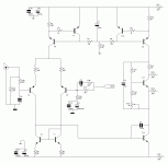
I made a few modification to the circuit according to Andrew comment.
I ad an input filter to prevent RF from gettig in.
I made a modification in CCS
According to me current in LTP is now 4mA an current in VAS is 13mA and both sources are fairly isolated from the other.
Are those modification done correctely
I ad an input filter to prevent RF from gettig in.
I made a modification in CCS
According to me current in LTP is now 4mA an current in VAS is 13mA and both sources are fairly isolated from the other.
Are those modification done correctely
Attachments
- Status
- This old topic is closed. If you want to reopen this topic, contact a moderator using the "Report Post" button.
- Home
- Amplifiers
- Solid State
- Blameless Amp layout


