means that only "Pb−Free Package" ?
In the datasheet is compared the THD values between unmatched and matched pairs.
But the matching procedure only takes into account the parameter "hfe" but not differences in variation of the Vbe value.
This I don't understand.
https://www.micro-semiconductor.com/datasheet/92-MJ21194G.pdf
I also don't see the pros and cons to the MJ15022, which is more expensive like the more recent ones.
https://www.onsemi.com/pdf/datasheet/mj15022-d.pdf
Last edited:
I was faced with the fact that many models of transistors are very curved, for example, these.
To check the parameters for complementarity, I typed two simple schemes.
As tests have shown, the transistor models are far from complementary, in this form they cannot be used in amplifier models.


To check the parameters for complementarity, I typed two simple schemes.
As tests have shown, the transistor models are far from complementary, in this form they cannot be used in amplifier models.
3. We would all like to avoid "it", and running class A is the only way I know of to completely avoid crossover distortion. If you want to go class A on a 200-watt power amplifier, be my guest. You are correct about crossover distortion being like a narrow spike as the signal goes through crossover. The reason the crossover distortion goes down as power goes up is mainly that the duty cycle of the spike becomes small compared to the duty cycle of the entire signal.
Cheers,
Bob
Class A is not the only way to reduce crossover distortion. The methods for reducing crossover distortion in class AB amplifiers are as follows:
- Fast negative feedback - inherent in amplifiers with a short signal propagation time (time Propagation Delay), Group Delay <100 NS;
- High frequency of the first pole, well above 20 kHz. In this case, the higher harmonics inherent in switching distortions enter the comparison unit without phase shift and are well compensated;
- The minimum possible value of emitter resistors (no more than 0.1 Ohm) or their absence (for example, in amplifiers with transistors of the Lateral type).
There have been many attempts to combat switching distortion in class AB amplifiers, but the most effective way was to increase the performance of the NFB by reducing the group delay. Here are some examples of output stages with different approaches
A few more examples, including refinement
https://www.diyaudio.com/community/...wer-follower-output-stage.222816/post-4209619


https://www.diyaudio.com/community/...wer-follower-output-stage.222816/post-4209619
fagos, you do not like the specifics of the output stages? What is the use of talking only about transistors without specific examples of their application. I just decided to join Bob Cordell's conversation about combating switching distortion. If you read my posts above, then you should have paid attention to mine post about his statementHave you forgotten the name of the topic? What does the circuitry of the output stages have to do with it? You yourself understand for sure that this is an offtop here.
Naim Audio's new output power devices:
under
https://www.naimaudio.com/sites/default/files/HFN_ LRes_Naim NAP 250 DR.pdf
I read this:
Originally launched some 40 years ago, Naim’s iconic NAP 250 power amp has witnessed numerous updates
of which these latest changes – new Statement-inspired output devices and discrete PSU regulation (hence ‘DR’)
– are among the most significant.
The new N-type (NA009N) and P-type (NA009P) power transistors are created by photoetching single wafers of silicon. This precise device matching ensures that current-sharing is wholly predictable across the NAP 250 DR’s full performance bandwidth.
Furthermore, these devices have a non-resonant epoxy case bonded onto a copper heat-spreader – even the legs are solid copper to reduce electromagnetic interaction under high current conditions.
Production volumes of the NA009 transistor are now sufficient to allow Naim the luxury of such components in its discrete PSU regulation, as opposed to using integrated devices for the same purpose.
Naim has always employed very tight PSU regulation, but the DR PSUs boast far lower noise.
Maybe a good replacement for some old mostly obsolete types mentioned in post #1 ?
Who know the manufacturer (no longer Semelab - so I think) ?
P.S.: This URLs don't provide the wanted information:
https://community.naimaudio.com/t/what-type-of-transistor-is-the-na009/10119?page=4
https://hifiandmusicsource.com/2016/09/the-joy-of-dr/naim-na009-transistor-2-hfams/
Attachments
Last edited:
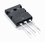
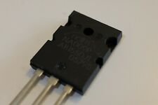
That is the older ON Semiconductor package. New ones (right) are all shipping in the Fairchild style package, which was re-optimized for high voltage use.
They are probably MJL3281 or 4281. Whether they are specially selected parameters, anyone’s guess because they tightly control customer and internal IP. Considering the Naim design philosophy probably NOT MJ21194 or variant thereof.
They are probably MJL3281 or 4281. Whether they are specially selected parameters, anyone’s guess because they tightly control customer and internal IP. Considering the Naim design philosophy probably NOT MJ21194 or variant thereof.
Attachments
"The new N-type (NA009N) and P-type (NA009P) power transistors are created by photoetching single wafers of silicon. This precise device matching" ...
errr... this is how most transistors are made. Along with a few other process steps.
Matching is more to do with doping and processing parameters rather than layout, although layout might be used to optimise a gain.
errr... this is how most transistors are made. Along with a few other process steps.
Matching is more to do with doping and processing parameters rather than layout, although layout might be used to optimise a gain.
These are probably versions of a well-known transistor manufacturer with a little bit of selection and marketing spin. I can't tell whether they are BJT or lateral MOSFETs (vertical MOFETs less likely). The identification numbers on the parts are somewhat reminiscent of those on the Exicon lateral MOSFETsNaim Audio's new output power devices:
under
https://www.naimaudio.com/sites/default/files/HFN_ LRes_Naim NAP 250 DR.pdf
I read this:
Originally launched some 40 years ago, Naim’s iconic NAP 250 power amp has witnessed numerous updates
of which these latest changes – new Statement-inspired output devices and discrete PSU regulation (hence ‘DR’)
– are among the most significant.
The new N-type (NA009N) and P-type (NA009P) power transistors are created by photoetching single wafers of silicon. This precise device matching ensures that current-sharing is wholly predictable across the NAP 250 DR’s full performance bandwidth.
Furthermore, these devices have a non-resonant epoxy case bonded onto a copper heat-spreader – even the legs are solid copper to reduce electromagnetic interaction under high current conditions.
Production volumes of the NA009 transistor are now sufficient to allow Naim the luxury of such components in its discrete PSU regulation, as opposed to using integrated devices for the same purpose.
Naim has always employed very tight PSU regulation, but the DR PSUs boast far lower noise.
Maybe a good replacement for some old mostly obsolete types mentioned in post #1 ?
Who know the manufacturer (no longer Semelab - so I think) ?
P.S.: This URLs don't provide the wanted information:
https://community.naimaudio.com/t/what-type-of-transistor-is-the-na009/10119?page=4
https://hifiandmusicsource.com/2016/09/the-joy-of-dr/naim-na009-transistor-2-hfams/
Cheers,
Bob
In post #1 I have listed various families and I note, that the values for highest ft are not in an outline like TO-3.
Currently I have an power amp device on the desk with output power devices in a TO-3 outline.
Unfortunately the surface is sanded, so that I haven't any possibility to read the type resp. model.
Actually only this brands and types exist in a TO-3 outline:
1) ST:
2ST5949/2ST2121 250V 17A 250W hfe: 35-160 25MHz TO-3/TO-204
2) ON-Semi:
MJ21195/MJ21196 250V 16A 250W hfe: 25-75 5MHz TO-3/TO-204
MJ21193/MJ21194 250V 16A 250W hfe: 25-75 5MHz TO-3/TO-204
or its predecessors MJ15003/15004 with ft of only 3 MHz - go to
https://pdf1.alldatasheet.com/datasheet-pdf/view/4798/MOTOROLA/MJ15003.html
The output buffer is executed as compound (Sziklai-) darlington.
From this point of view, the ST version with a higher value for Ft would be the better choice.
Unfortunately I don't know currently available successors for this obsolete type.
Is there a possibility to find out, what type is in use through certainly measurements by a transistor tester ?
Last edited:
- Home
- Amplifiers
- Solid State
- bipolar (BJT) transistor families for audio power output stages