It looks like there are 2 pieces to your post. The first piece has to do with the negative feedback process itself and what I have called re-entrant distortion in my book. The second piece has to do with class AB crossover distortion.
The first piece is a very old argument that goes back at least to Baxandall. It is the old "the signal goes 'round and 'round" argument. There is some nuggets of truth in the argument, but in practice it is easily shown that the argument does not hold enough water in most situations. This is easily proved by simulation of simple amplifiers to complete amplifiers. The simulations, of course, provide all of the pertinent information on the amplitudes of the different harmonics. This is discussed at length in my book and the results of simulations are shown. Interestingly, as the amount of NFB is increased from a very small value to a large value, the amplitudes of the higher harmonics begin to increase, as expected from this argument. I seem to recall that the effect was strongest at low levels of feedback, on the order of 10-20 dB. Beyond that, the increased NFB decreases all harmonics to very small numbers. The lesson here is that while anecdotal arguments are sometimes useful for insight, one really needs to plug in the real numbers to see what is going on and what is sufficient.
Your second argument about crossover distortion is largely correct, in my opinion. Although arguments about its audibility and badness as a function of level can be described as subjective, I think that those conclusions are correct. More to the point, an optimally-biased class AB output stage (described by Oliver long before Douglass wrote anything) actually operates at a quite low value of bias current. This is part of the problem. In theory, there should be about 26 mV across each emitter resistor to satisfy the Oliver Criteria. For 0.22-ohm emitter resistors, this comes out to only 118 mA quiescent current. This means that the class A region, where both output transistors are contributing transconductace, is no greater than 236 mA peak. This corresponds to 167 mA RMS, which will develop 1.34 V RMS across 8 ohms, corresponding to only about 223 mW.
But the reality is worse. For a real-world output circuit and imperfect output transistors, part of the effective Re is inside the transistor, due in part to ohmic emitter resistance, ohmic base resistance divided by beta, and ohmic base stopper resistance divided by beta. This "internal" effective ohmic emitter resistor counts as part of RE in satisfying the Oliver Criteria. This internal ohmic component could be as great as 0.1 ohm. In that case, with 0.22-ohm external RE, the RE for bias setting would be 0.32-ohm, calling for a lower "optimal" bias current of 26mV/0.32 ohm equals 81 mA, resulting in an even smaller class A region.
Now add program-dependent thermal variations that alter Vbe and gm of the output transistors, and you have an even more dynamic can of worms. While it is tempting to run the output stage hotter to obtain a larger class A region, in violation of the Oliver Criteria, gm doubling then comes into play, and it also creates nasty crossover distortion.
Reducing RE below 0.22 ohm can increase the allowable bias current corresponding to the Oliver Criteria, but thermal stability begins to suffer; and, of course, the relative significance of the internal transistor ohmic resistance becomes a larger portion of the effective RE. Even with a very good heatsink, I would be quite reluctant to go below 0.15 ohms for RE.
The most straightforward way to reduce crossover distortion, I think, is to use more output pairs that are optimally biased. Each doubling of the number of output pairs should approximately cut static crossover distortion in half. This presumes that there is plenty of turn-off current from the drivers and high ft in the output transistors to keep switching distortion (dynamic crossover distortion, as long ago described by Jim Bongiorno) low.
Cheers,
Bob
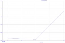
Simulation of my bridge amp in Microcap12
Nice, did you publish a schematic, or build it?
1. The first piece is a very old argument that goes back at least to Baxandall. It is the old "the signal goes 'round and 'round" argument. There is some nuggets of truth in the argument, but in practice it is easily shown that the argument does not hold enough water in most situations.
2. While it is tempting to run the output stage hotter to obtain a larger class A region, in violation of the Oliver Criteria, gm doubling then comes into play, and it also creates nasty crossover distortion.
3.The most straightforward way to reduce crossover distortion, I think, is to use more output pairs that are optimally biased. Each doubling of the number of output pairs should approximately cut static crossover distortion in half.
1. Of course the feedbackloop thingy settles to a final value if there is enough time. Which means that if the frequency is to high or the amp is to slow, input stage will not be able to track the signal.
I dont claim feedback is bad, just say it can not cure everything.
2. Unfortunately there are 3 different situations. Predominantly current from NPN when the signal is positive, then NPN and PNP sharing in the crossover region, then current sinking PNP in the negative part. Again, unfortunately, the PNP is never 100 % true complementary to the NPN.
This crossover distortion is not like normal harmonics, it is more like a short spike of trash. Low idle means a more strong but short spike, while a larger classA region makes the spike broader but less strong.
So, what is tried to be found here, is a - huhu - compromise.
3. I think avoid is better than reduce if reduce dosnt mean eliminate.
Nice, did you publish a schematic, or build it?
I hope the day will come when I can show that schematic.
We all know simulation is one thing, reality is another

Yes, built already and still has some issues.
1. Of course the feedbackloop thingy settles to a final value if there is enough time. Which means that if the frequency is to high or the amp is to slow, input stage will not be able to track the signal.
I dont claim feedback is bad, just say it can not cure everything.
2. Unfortunately there are 3 different situations. Predominantly current from NPN when the signal is positive, then NPN and PNP sharing in the crossover region, then current sinking PNP in the negative part. Again, unfortunately, the PNP is never 100 % true complementary to the NPN.
This crossover distortion is not like normal harmonics, it is more like a short spike of trash. Low idle means a more strong but short spike, while a larger classA region makes the spike broader but less strong.
So, what is tried to be found here, is a - huhu - compromise.
3. I think avoid is better than reduce if reduce dosnt mean eliminate.
1. The matter of the input stage not being able to track the signal is one of slew rate limiting, not the re-entrant distortion mechanism you mentioned.
2. The crossover distortion will occur even if the NPN and PNP transistors are perfect complements with perfect exponential Ic vs. Vbe characteristics. Do a wingspread simulation with ideal transistor models and you will see it clearly.
3. We would all like to avoid "it", and running class A is the only way I know of to completely avoid crossover distortion. If you want to go class A on a 200-watt power amplifier, be my guest
. You are correct about crossover distortion being like a narrow spike as the signal goes through crossover. The reason the crossover distortion goes down as power goes up is mainly that the duty cycle of the spike becomes small compared to the duty cycle of the entire signal.Cheers,
Bob
My humple understanding:
Lets say the amp has pure K3 distortion due to the nonlinearity of the output stage.
With a 1 kHz test signal that is 3 kHz, which travels via feedback to the diff amp.
To compensate, the diff amp adds an amount of 3 kHz inverted to the signal.
So instead of only 1 kHz, the output stage is now dealing with 1 kHz and 3 kHz.
That 3 kHz should completely cancel the original K3 of the output stage.
However, it doesnt, instead there will be generated a new K3 which is now 9 kHz and a fraction of the original 3 kHz remains.
Now we have 1 kHz + harmonics 3 kHz + 9 kHz.
And there are more iterations resulting in even higher harmonics.
Maybe what he liked to say was... If the amplifier has class B crossover distortion in open loop and you add feedback... The sonic signature will not go away completely... It will remain, plus it will be altered to some extend by the higher harmonics added... So a classB amp will never ever become a classA amp.
The problem that I see, is that ClassB/AB has this distortion at low levels which is exactly the oppusite from what we have in nature.
Every instrument, voice, speaker, microphone and the ear will distort more at higher levels.
Thats what the brain is used to, so crossover distortion is unnatural to our hearing and we perceive it as fatigue and unpleasant.
Same problem with most multibit DACs at low level.
Similar issue with metal speaker cones, they may have some good properties but they have harsh resonances, you can try to flatten that resonant peak or put it a bit outside the used frequency band, but the sonic signature will never disappear.

In this case this URLs are of interest:
kind of distortion
http://www-f9.ijs.si/~margan/Articles/Class_B_Dist.pdf
post #31
margan : non switching class B
and
Common-Mode Distortion
If I compare the character of distortions the mentioned diagrams of the URLs in follow (fundamental notched out), I notice a simple rule: sine wave character, good sound, saw-tooth/triangle character or other large differences to sine wave character, not good sound in the high- and midrange frequency area. Both low and very low THD+N value itself says nothing about the sound quality, which is assessed in listening tests.
In the meantime I can see which model would no longer unpack and connect for checking the sound quality:
Fig. 5+6
Bel Canto e.One S300iu integrated amplifier Measurements | Stereophile.com
Fig. 8
Page not found | Stereophile.com
Fig. 8 (class-D)
https://www.stereophile.com/content/ps-audio-stellar-m1200-monoblock-power-amplifier-measurements
Fig. 6 (class-D)
https://www.stereophile.com/content/bel-canto-ref1000m-monoblock-power-amplifier-measurements
Fig. 4 (class-D)
https://www.stereophile.com/content/yamaha-mx-d1-digital-power-amplifier-measurements
Fig. 9
https://www.stereophile.com/content/yamaha-s3200-integrated-amplifier-measurements
Fig 13
https://www.stereophile.com/content/balanced-audio-technology-vk-56se-power-amplifier-measurements
Fig. 11
https://www.stereophile.com/content/mcintosh-laboratory-mc462-power-amplifier-measurements
Fig. 4
https://www.stereophile.com/content/pass-aleph-12-monoblock-power-amplifier-measurements
Fig. 8
https://www.stereophile.com/content/pass-laboratories-xa2008-monoblock-power-amplifier-measurements
Fig. 5
https://www.stereophile.com/content/threshold-t-200-power-amplifier-measurements
Fig. 7
https://www.stereophile.com/content/soulution-710-power-amplifier-measurements
Fig. 8
https://www.stereophile.com/content/ps-audio-stellar-m700-monoblock-power-amplifier-measurements
Fig. 7
https://www.stereophile.com/content/halcro-dm38-power-amplifier-measurements
Fig. 4
https://www.stereophile.com/content/accuphase-m-2000-monoblock-power-amplifier-measurements
Fig. 7
https://www.stereophile.com/content/mark-levinson-no536-monoblock-power-amplifier-measurements
Fig. 5
https://www.stereophile.com/content/class233-audio-fifteen-power-amplifier-measurements
Fig. 5
https://www.stereophile.com/content/bryston-7b-sstsup2sup-monoblock-power-amplifier-measurements
Fig. 6
https://www.stereophile.com/content/bryston-3b-st-power-amplifier-measurements
Fig. 3+4
https://www.stereophile.com/content/krell-ksa-250-power-amplifier-measurements
Fig. 9
https://www.stereophile.com/content/musical-fidelity-ams100-power-amplifier-measurements
Fig. 10
https://www.stereophile.com/content/naim-supernait-integrated-amplifier-measurements
fig. 11
https://www.stereophile.com/content...e-160m-monoblock-power-amplifier-measurements
Fig. 11
https://www.stereophile.com/content/lamm-ml22-monoblock-power-amplifier-measurements
Fig. 4
https://www.stereophile.com/content/yba-passion-1000-monoblock-power-amplifier-measurements
Fig. 9
https://www.stereophile.com/content...e-160m-monoblock-power-amplifier-measurements
Fig. 7
https://www.stereophile.com/content...perion-monoblock-power-amplifier-measurements
Fig. 8
https://www.stereophile.com/content/doshi-audio-monoblock-v30-power-amplifier-measurements
Fig. 13
https://www.stereophile.com/content/balanced-audio-technology-vk-56se-power-amplifier-measurements
Fig. 8
https://www.stereophile.com/content/nad-masters-series-m22-power-amplifier-measurements
Fig. 5
https://www.stereophile.com/content/graaf-gm-200-otl-power-amplifier-measurements
Fig. 4
https://www.stereophile.com/content...monoblock-power-amplifier-measurements-part-2
Fig. 11
https://www.stereophile.com/content/mcintosh-laboratory-mc462-power-amplifier-measurements
Fig. 3+4
https://www.stereophile.com/content/yamaha-mx-d1-digital-power-amplifier-measurements
Fig. 6
https://www.stereophile.com/content/bel-canto-ref1000m-monoblock-power-amplifier-measurements
fig. 7
https://www.stereophile.com/content/avm-ovation-ma82-monoblock-power-amplifier-measurements
Fig. 4
https://www.stereophile.com/content/jeff-rowland-design-group-model-1-power-amplifier-measurements
Fig. 5
https://www.stereophile.com/content...oup-model-2-power-amplifier-1995-measurements
Fig. 7
https://www.stereophile.com/content/first-watt-sit-3-power-amplifier-measurements
Fig. 10
https://www.stereophile.com/content/schiit-audio-aegir-power-amplifier-measurements
Fig. 10
https://www.stereophile.com/content/theta-digital-prometheus-monoblock-power-amplifier-measurements
All Class AB and Class D versions exhibit visible high-order distortion despite extremely low THD-N values in some cases.
OTOH - not extremely low THD-N values on models with higher idle current in the output stage definitely sound good. H2 and H3 distortion components are only faintly audible and do not interfere with listening comparisons.
1. The matter of the input stage not being able to track the signal is one of slew rate limiting, not the re-entrant distortion mechanism you mentioned.
2. The crossover distortion will occur even if the NPN and PNP transistors are perfect complements with perfect exponential Ic vs. Vbe characteristics. Do a wingspread simulation with ideal transistor models and you will see it clearly.
3. We would all like to avoid "it", and running class A is the only way I know of to completely avoid crossover distortion. If you want to go class A on a 200-watt power amplifier, be my guest
1. I was not accurate here, I ment the whole process inside the arrangement of different stages including slew rates, time for the electrons to travel through the feedback resistor and so on.
2. PNP and NPN not being perfectly matched is a "nice" add on to the issue, on top.
3. I dont need 200W, honestly. Power up - distortion down, thats the unnatural thing.
The first watt could be the most important

I hope you can make it work!
The non-switching schemes are attractive but in reality they all end up causing more distortion, none of them work.
The non-switching schemes are attractive but in reality they all end up causing more distortion, none of them work.
.....ClassB/AB has this distortion at low levels which is exactly the oppusite from what we have in nature.
Every instrument, voice, speaker, microphone and the ear will distort more at higher levels....
There ARE examples of low-level "distortion" in nature.
When you have a cold, or phlegm in your throat, your speech/song is "rough" at low level but clears-up as you maintain high volume.
There are similar issues with instrument reeds/throats/cups, the oscillation is impure at low level and clears-up with more output.
These "rough" sounds are usually understood to be "bad", even "sick", so we are annoyed when our amplifier does it to known-clear recordings.
If the high power, high ft transistors that you want are not available, why not put a load of small and fast ones parallel ?
And what about the Sony TA-N7B V-Fet approach ?
It uses the V-Fets only as heat dissipating cascode, so the output device can be a faster low power transistor, 2SC1173.
You can download service manual with nice explanations from elektrotanya.
And what about the Sony TA-N7B V-Fet approach ?
It uses the V-Fets only as heat dissipating cascode, so the output device can be a faster low power transistor, 2SC1173.
You can download service manual with nice explanations from elektrotanya.
2 stage Amplifier with diff stage gain X
3 stage amplifier with diff stage gain X/2 and VAS gain X/2
Is it easier for the diff input stage of the 2 stage amp to control / correct the output stage ?
Because in the 3 stage amp there is another multiplier ?
Or is it more difficult for the diff input stage of the 2 stage amp to obtain a large voltage swing ?
Compare that with a mechanical lever, where in the first case from the standpoint of the diff output node, both sides have the same length and in the second case the other side is much longer and the lever (VAS) behavior is difficult to predict.
Last edited:
From the standpoint of the feedback node, in the first case the other side of the lever is "much" longer, in the second case the other side is only "longer" but again coupled to another similar lever that has a not exactly predictable behavior. In both cases the last end must control the output stage.
Which types in the TO-3 outline are currently being manufactured ?
Unfortunately the mentioned as follow unfortunately all out of production (obsolete):
1) 2ST5949/2ST2121 250V 17A 250W
https://www.st.com/resource/en/datasheet/cd00178796.pdf
https://www.st.com/resource/en/datasheet/cd00171926.pdf
2) MJ21195/21196 and MJ21193/21194 250V 16A 250W
https://www.onsemi.com/pdf/datasheet/mj21195-d.pdf
https://www.onsemi.com/pdf/datasheet/mj21193-d.pdf
3) additional this older types: MJ15022/15023 200V 16A 250W
https://www.onsemi.com/pdf/datasheet/mj15023-d.pdf
https://www.onsemi.com/pdf/datasheet/mj15022-d.pdf
- Home
- Amplifiers
- Solid State
- bipolar (BJT) transistor families for audio power output stages