now that we've veered all the way to Bangalore in order to get from Paris to Nice
for Overkill Steampunk
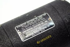
Well, this is a new ballgame. What is needed is a WWII Dynamotor for 600V.
It could provide sound effects at turn-on and pre-charge the capacitors up to 600V before the Mercury Vapor rectifiers come on line.
If it weren't for the constant whining noise, the dynamotor could power the whole thing. But it will provide a nice revving up effect during warm-up to keep everyone entertained until the main power and tubes come up.
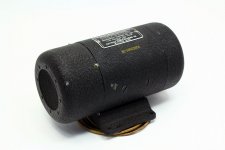
Could copper plate the dynamotor for that retro look. Although the black krinkle paint looks "military".
It's even cheap:
Vintage Continental Electric Radio Dynamotor DMF519H US NAVY WW2 | eBay
Attachments
Last edited:
Hmm. An interesting idea, though I'd have to keep the b+ supply disconnected from the load, then disconnect the dynamotor from the b+ supply and shut it off, then turn on the main b+ supply (soft started to bring cap from 600V to 800V), then connect the load.
While not awfully difficult, that is a number of extra relays, and it would slam the output tubes, pass tubes, preamp and driver tubes with full b+ instantly.
If I leave the load connected, then at the moment of transition from dynamotor to main b+, the brief period where neither supply is connected would likely discharge that cap significantly, only for it to be surge charged by the rectifiers.
There are two small blowers that will give a similar sound. Not to mention the clicking of relays and glowing bulbs, as the filament stages soft start (in series with light bulb) then come up fully, triggering the next phase, then b+ soft start and full power. It'll be quite active on its own.
Just needs a SS rectifier on the output of the Dynamotor. When the 800V comes up, the rectifier will reverse bias, disconnecting the dyno. Can power down the dyno then. Of course you will soon need a fork lift to move all this.
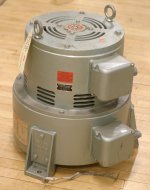
A better approach would be to use a 400 or 800 Hz 3 phase dynamotor in the basement. Then the 3 phase 400Hz power could be up V converted by some small 400 Hz xfmrs on the chassis. The 3 phase would eliminate most of the ripple after rectification, so filtering would be easy. There are some 60 Hz to 400 Hz (or 800) brushless single shaft motor generators made by Georator.
Unfortunately, these are too noisy to have near the amplifier too. Basement.
Attachments
Last edited:
What is needed is a WWII Dynamotor for 600V.
I found some Carter 600 Volt dynamotors and some TV sweep tubes under a bench in the Pearce Simpson CB radio warehouse in Miami when it shut down around 1980. I wonder what they were doing with those.......my good ol boy friends found two useful applications for them, electric fishing, and getting nightcrawlers out of wet ground rather quickly.
Hmm. Now that's where things are getting a bit out of hand, and if I was going to use 3 phase I'd just do a 60Hz motor generator and it be the main power for the b+ supply.
Not to mention it would violate the "absolutely no sand anywhere" clause if this amp. Even the filament rectifiers are tungar bulbs.
I could build some sort of thyratron motor controller to slowly bring up the blowers for that similar sound effect, also would light up.
In the future I'd like to design a single phase to three phase switch mode converter, so that I can build 3 phase devices without the heavy converter. Basically a single phase to 3 phase vfd, without the variable part. And a proper sine wave.
EDIT: when you said basement I thought you meant the bottom of the amp, not literally the basement. I unfortunately don't have a basement, but I may build a rotary converter and put it in the shed.
Last edited:
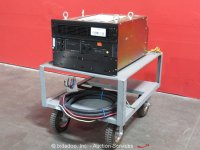
If the SS power supply is BIG enough, it just looks like the power company.
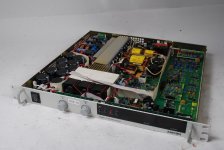
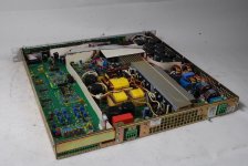
Sorensen 10 KW 600V 16 Amp power supply, comes with a roll around cart, from Boeing Co., just sold for $29
Sorensen PRO600-16T5M5 DC Power Supply 600V Industrial Test Cart Manual bidadoo | eBay
Sorensen 10 KW 600V 16 Amp power supply, comes with a roll around cart, from Boeing Co., just sold for $29
Sorensen PRO600-16T5M5 DC Power Supply 600V Industrial Test Cart Manual bidadoo | eBay
Attachments
It's a regulated power supply, SS. With adjustable voltage and current limiting. That one does run off 3 phase input power however.
Not too practical for home use.
Probably direct 3 phase rectification to DC/capacitors, then a big switching PWM power unit. It's got the same knobs and front panel stuff as the Xantrex XHR series, so it probably was made by them. Usually has GPIB/RS-232 interfacing on the back for remote control. The XHR series is all Mosfet stuff with PFC, power factor correction, on the input for sinusoidal current draw from the line. Millisecond response time regulation.
Last edited:
Interesting indeed. Would this setup work? One has a filtered dc supply, then has 3 triodes with each anode to the leg of a 3 phase mains transformer, and b+ to the center tap. Each grid is fed with a leg of 3 phase 60Hz from a small 3 phase alternator (car alternator without diodes, stepped up to the proper grid p-p voltage for the triode). Would this make for a tube 3 phase inverter?
So you are trying to get a DC controlled voltage out from the common cathodes? I think you will need either a pulse width control for the grid pulses, or a sinusoidal phase control (3 phases) between the grid drives and the anode voltages. Could derive that from the anode voltages. But you will end up with pulsed outputs, not nice 3 phase sine waves.
Unless you run it all in a linear 3 phase mode to get attenuated 3 phase sine waves out. That will still heat up the tubes as hot as the usual DC regulator approach.
Hopefully you are not planning on running a vehicle in idle whenever powering the amplifier.
You could run -two- 3 phase generators with a variable phase between them. (adjustable slack in one drive belt via a set of idler pulleys) Then sum the AC voltages of both (each phase separately, then rectify). Not going to be fast V regulation with mechanical belt control. (or use a differential gear arrangement for one drive, adjust the third, differential, shaft position for phase control)
Easier to just electrically control the field winding on the 3 phase generator to control the AC amplitudes. (just like car alternator regulators work) Then just 3 phase rectify the AC phases and sum thru a small inductor into a big capacitor. The non laminated steel pole pieces on the field/armature of auto alternators does not allow for fast regulation however. At least the fast AC ripple filters out easily. If the DC side of the 3 phase supply has big enough capacitance, then fast V regulation of the alternator field might not be needed.
Last edited:
Essentially trying to amplify a 60Hz signal with 3 channels (3 phases), so a single phase ac source can be rectified, then give 3 phase 60Hz sine wave out. Instead of audio transformers, mains transformers can be used since it's 60Hz. Basically a rectifier and 3 phase inverter, but with tubes. In theory, if the grid voltage is run through a rheostat, couldn't output voltage be varied? Essentially a 3 phase converter with no moving parts.
I intend to use a hellcat v8 at 3600rpm to drive the alternator
I intend to use a hellcat v8 at 3600rpm to drive the alternator
Last edited:
Vehicle alternators have rather more then two magnetic poles on them, so you can run the engine at near idle speed to get 60 Hz 3 phase.
You could just use a synchronous 60 Hz 3 phase motor driven by one phase and a capacitor to another phase for starting. Once started and up to speed, you can draw big 3 phase power off them. These things are commercially available, rotary phase converters. Often sold for running lathes or milling machines (supplied with 3 phase motors) off of single phase power. Of course they make some whining noise similar to a motor-generator. Check ENCO for such accessories. They don't provide for voltage amplitude control however (that I am aware of anyway). You need the separate motor and generator (with a DC field winding) to get AC voltage control.
You could just use a synchronous 60 Hz 3 phase motor driven by one phase and a capacitor to another phase for starting. Once started and up to speed, you can draw big 3 phase power off them. These things are commercially available, rotary phase converters. Often sold for running lathes or milling machines (supplied with 3 phase motors) off of single phase power. Of course they make some whining noise similar to a motor-generator. Check ENCO for such accessories. They don't provide for voltage amplitude control however (that I am aware of anyway). You need the separate motor and generator (with a DC field winding) to get AC voltage control.
Last edited:
I think you're missing what I'm trying to say. I'm not using the car alternator to power anything. It's just to provide a 3 phase ac signal where none exists. It's the smallest 3 phase generator I know of.
Essentially imagine a 3 channel audio amp, fed with a 60Hz ac signal. It would provide a 60Hz 3 phase output, which could be run through transformers and go power whatever needs 3 phase power. Would push pull be needed for a clean sine wave output on each channel?
Thus single phase ac power can be rectified, then inverted to 3 phase ac. Just with tubes. Impractical and silly, but I don't see why it isn't possible.
I suppose so. Not going to be very efficient unless PWM switching type amplifiers are used (Crown Amplifiers, SS Mosfet HF PWM). Ie, class D amplifiers.
What you are describing (with 3 phases) is called a 3 phase variable speed motor controller. Not too expensive used on Ebay. Would have to hack into one to control the AC voltage, without changing the frequency along with it.
You could get the 3 phase drive signal by using an Eprom with a digitally encoded sinewave, and 3 D/A converters fed from different phases in the data readout. A constant HF clock signal running a set of counters to address through the Eprom sequentially. There are wave generator test equipment that can do that too. They use a Ram chip with a user specified waveform encoded on it. D/A readout of the continuous waveform.
Last edited:
There is a type of PWM converter that is HF ripple free, called the Cuk converter. And some other related ripple free converters. (so you don't have to use 3 phase)
Most simple PWM converters need filtering to remove the severe switching ripple, but not these. Smooth DC like waveform output, with smooth V ramping during variable control. Which can be phase controlled for output V regulation. They have been used to make class D audio amplifiers directly, using fast phase control. They (like most PWM stuff) have high output impedance however, so N feedback is required to fix that.
Getting the N Fdbk to work well is the big trick for dynamic output (audio). Tripath Class T amplifiers made a big advance there by using proportional, integral, derivative (PID) predictive N Fdbk. (a common technique used for process control)
Last edited:
- Status
- This old topic is closed. If you want to reopen this topic, contact a moderator using the "Report Post" button.
- Home
- Amplifiers
- Tubes / Valves
- Big Tube based voltage regulator