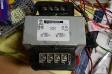
Power supply is 1920V C.T. @ 1A xfmr (that is two 480v control transformers in series for each leg btw) into 2 parallel 866As (per leg) with a .33H choke in series with each anode for current sharing.
Filter is 1H-2uF-1H-6uF LCLC.
Have you simulated this circuit with PSUD or another simulator? 1920 CT into a filter that's somewhere between choke and cap input (chokes too small), should result in over 1KV of raw B+. Instead of using 4 industrial transformers, connect the CT of one of them to ground, and hang another one off of each leg. That makes 1440 CT.
I rarely use regulated plate supplies in tube amps. If the amp runs pentode mode, I will regulate the screen and bias supplies. Triode or UL, I don't regulate any of them.
Want a big amp with big pretty tubes, run 4 X 4D32's in pentode mode in each channel. The data sheet implementation will get you 250 WPC from 600 volts.....bending the rules a bit will get you 300 to 400 watts on 650 volts. Less voltage, less stress on the parts and you can still use those glowing 866's. The screen regulator can be built with an EL34 and some wimpy tube can be used for the bias regulator.
So… knowing in advance that I'm probably destined to get covered in rotten tomatoes and other thrown vegetables, you've (OP) stated a goal, but defined the tech for reasons that don't hold up compared to the alternatives.
You're building a regulated power supply.
You're wanting to employ a regulation device for series style regulation.
And you're selecting tubes … because … you want to?
On the surface there are 3 problems, only one of which i've not read yet in trawling (not trolling) this thread.
Nº 1: highly elevated cathode (series reg) requiring separate power supply.
Nº 2: Modest available current handling in reasonably priced tubes
Nº 3: Not particularly excellent transconductance for Big Boy tubes. mA/V, etc.
Don't know if all y'all talked about that last one or not, or even the first one. But seriously the simple answer is out in front: The modern MOSFET answers all these issues, including rather incredible resilience to over current and so on, easily. (GoatGuy ducks in anticipation of chucked fermented vegetation). Why the tube route? Just to have a big (and yes! impressive!!!) piece of glowing glass tubery as the centerpiece of a massive amplifier?
Hey, I get it if that's the real answer. I do. People “chop” their Mac trucks, their Chevy '59 cars, their Delta chugging power boats. With sparkly fingernail red paint and all the rest. It's a hobby. I get it.
But if you're just trying to otherwise solve this one rather idealized and laudable goal, that of substantial ripple reduction thru series regulation, well … silicon carbide turns out to be a friend. Transconductance not measured in milliSiemens (mA/V) but full on Siemens (A/V) transconductance. Talk about regulation! Totally flat staircase curves as well. Again… excellent ripple reduction and regulation. Multi-ampere pass current capacity. Nominal 200+ W dissipation with heat sinks, and kilowatt peaks handled without a hiccup.
And no extra hi-pot insulated filament winding either. Yet another heat source quashed.
Anyway… I'm keeping the titanium armor on until the tomato-in-trebuchet crowd dissipates somewhat. Ready, … aim, … fire!
GoatGuy
Man, is it just me, or is 2018 the year of the Mosfet? Simple mosfet regulators seem to be the most useful answer/alternative in a ton of threads lately.
I've already done a handful of mosfet ripple filters, and regulators, and even at 500mA, dropping 150 volts they are hard to beat, with a simple junker heatsink, even.
I agree wholeheartedly with goat (as... usual? Huh) that a mosfet makes much more sense here, and I'm a die hard tube guy. It's a lofty goal to go all tube for such a project, but I wouldn't.
Last edited:
Skip the regulator altogether.
The latest Sola constant voltage xfmrs are rated for 1% regulation. CVS types are quieter than the old CVN types. Although you may still want to put it in the basement for HIFI.
Use two 500 Watt ($75) xfmrs for series connected 240VAC secondaries to get 600VDC.
SOLA GS CVS 500VA CONSTANT VOLTAGE TRANSFORMER 23-00150-0800-23 43 TYPE 95-520 V | eBay
specs in last pic there.
Mmmm… no, I don't think so. But there are more of us die-hard builders who see their benefit(s).Man, is it just me, or is 2018 the year of the Mosfet?
Simple mosfet regulators seem to be the most useful answer/alternative in a ton of threads lately.
I've already done a handful of mosfet ripple filters, and regulators, and even at 500mA, dropping 150 volts they are hard to beat, with a simple junker heatsink, even.
I agree wholeheartedly with goat (awe...) that a mosfet makes much more sense here, and I'm a die hard tube guy. It's a lofty goal to go all tube for such a project, but I wouldn't.
Again, I think it comes down to STATING CLEARLY either that window dressing is what is desired (giving rise to magnificent pieces of glass), or excellence-in-power-supply is catamount. Wherein series regulation with crystals is King.
There are other solutions than MOSFET, but there are scant advantages. Bipolar has the advantage of not having a sensitive-to-static gate. But again, modern MOSFET devices generally handle all that without much designer consternation anymore. The disadvantage of BJTs is that they're usually not very aggressive current amplifiers at power. hFE of 25 or so. So that that in turn requires the ''reference base voltage source'' to actually be a non-zero power voltage source.
I (can, advise, and have) used a simple 11 kohm + 110 kohm voltage divider (having a Thevenin equivalent source voltage of 91% of B+, and a Thevenin series resistance of 10 kohm) as a source voltage for a NPN hi-volt base. Emitter follower. Worked out pretty well, actually. At 300 V B+ raw, got 265 VDC at the emitter. Was delivering about 225 ma nominal, for a single transistor would have required 9 ma into base; too much. So did a Darlington with a pair of the same BJTs, and got down to 0.36 ma. At 10 kohm equivalent resistance, that's 3.6 volts of drop. RC = 0.22 sec, using 22 uF capacitor for smoothing.
But MOSFETs consume 0 amps. They're simply elegant.
GoatGuy
Last edited:
Skip the regulator altogether. The latest Sola constant voltage xfmrs are rated for 1% regulation.
You seem to have missed the point, actually.
Ling and I aren't going on about absolute regulation. It isn't about regulation per se, it is about using some sort of active device in a source/emitter/cathode follower configuration to significantly squash ripple. Like by –40 dB or better. It doesn't replace the usual front end rectifier stack → capacitors → smallish inductor → capacitors business.
GoatGuy
Well then get the old CVN type Sola CVT, even cheaper, and they put out square wave for DC rectification. What ripple? Even if you want the residual down to mVs, a Mosfet regulator after the CVT will only have to drop 2V.
How much is just the 1 KW HV xfmr going to cost compared to $100 for the whole thing.
How much is just the 1 KW HV xfmr going to cost compared to $100 for the whole thing.
Last edited:
Don't know if all y'all talked about that last one or not, or even the first one.
All 3 points have been touched in this thread. The H-K issue in the pass tube was discussed in post #34 where several tubes with sufficient current handling ( 3 devices) were listed. The OP stated that he would tie the heater to the cathode in post #46. Three of the larger TV sweep tubes needed to handle 1 amp continuously would have 36,000 mMhos of Gm, certainly not in mosfet land, but good enough for a series regulator.
But before discussing any of this, I made this statement in post #20
Really, If I was making a regulator to turn 800 volts into 600 volts at 1 amp I would use either a 2SK3581 (600V @43A) or a 2SK3549 (900 V @ 10 A), as I have some of both.....
The OP wants to pimp out his amp with big tubes.....OK, I get that too, I would just put the cool looking tubes in the output stage and dispense with the plate voltage regulator, or hide the mosfets under the deck if it were my build.
Well then get the old CVN type Sola CVT, even cheaper, and they put out square wave for DC rectification. What ripple? Even if you want the residual down to mVs, a Mosfet regulator after the CVT will only have to drop 2V.
How much is just the 1 KW HV xfmr going to cost compared to $100 for the whole thing.
No free lunch, smoking-amp. In case you haven't actually used SOLA constant voltage transformers, the “lunch fare” is heat. The full-saturation reluctance of the gapped cores causes overcurrent (primary side) heating. I do however “get” what you're recommending.
Supposing - just so we can turn the topic back to the more conventional case - supposing that we're using non-CVT transformers and ordinary 50 or 60 Hz line power, and full-wave rectification, there still is from 8.3 to 10 milliseconds between rectification peaks. If one's drawing what is it, 500+ mA?, and the first condenser reservoir is only 10 μF, the (dV/dt = i(t)/C) is 0.5 ÷ 10×10⁻⁶ → 50,000 v/s. You've got say 8.3 msec so, 50,000 × 8.3×10⁻³ = 50 × 8.3 = 400 volts ripple. This is not a sophisticated mathematical treatment, but a “stupid one but good enough”.
Reversing the calculations to have a manageable amount of primary-condenser ripple (say 3%?), we get 800 volts × 3% = 24 volts. We've got 8.3 milliseconds, so 24 ÷ 0.0083 = 2900 v/s droop rate. 500 ma still? OK, (dV/dt = i(t)/C → C = i(t)/(dV/dt)) so C = 0.5 ÷ 2900 = 172 μF. Ah… better.
Closest larger value is a good primary guess, especially if cheap. 220 μF. Made from a pair (series) of 470 μF @ 450 volt conventional caps and a resistor-volt-balancing parallel ladder.
Now we have 24 volts of primary ripple. The inductor+next-capacitor will drop that another 90%. 2.4 volts or so left. Since we're not going to use absolute regulation, but "90%" relative regulation, 80 volts below 800 volts is quite a margin. The regulator is going to dissipate (P = ΔVI = 80 × 0.5 → 40 watts)
Again … "no big deal". The true cost of the solution ain't $100 either. Popular tough-as-nails MOSFETs run what, less than $2 each? Heat sinks - even if you feel compelled to buy a pretty one, are usually less than $20 ea. Resistors … almost free. A 22 μF stabilizing capacitor, less than 2 bucks. ALL IN less than $20 if you're resourceful. You could even mount a pair of MOSFETs on the same heat sink, and have each one of them dropping half the 10%, effectively multiplying their ripple rejection by each individual factor. If one gives –30 dB, then 2 give –50 to –60 dB. Outstanding. For $5 more. Try that with inductors and capacitors!
Just saying.
Relative-reference regulation is great.
Absolute-reference regulation is awesome, but requires wider margins.
GoatGuy
All 3 points have been touched in this thread. The H-K issue in the pass tube was discussed in post Nº 34 where several tubes with sufficient current handling ( 3 devices) were listed. The OP stated that he would tie the heater to the cathode in post Nº 46. Three of the larger TV sweep tubes needed to handle 1 amp continuously would have 36,000 mMhos of Gm, certainly not in mosfet land, but good enough for a series regulator.
But before discussing any of this, I made this statement in post Nº 20
The OP wants to pimp out his amp with big tubes.....OK, I get that too, I would just put the cool looking tubes in the output stage and dispense with the plate voltage regulator, or hide the mosfets under the deck if it were my build.
I'm sorry - I missed reading your posts. My bad. I especially agree regarding “hiding the workhorses under the bling”. Works for me. People really aren't interested in what's under the hood. All nature of odd looking doodads can hide under the chrome-and-brushed-maple covers.
GoatGuy
The $100 figure was referring to the cost for two 500 VA CVN xfmrs. With square wave output, the Mosfet regulator can be rated for just 10 Watts then if used. I'm not sure about the efficiency of the older CVN Xfmrs, but Sola quotes 90% efficiency (full load) for the new CVS xfmrs. So around 100 Watts heat from the xfmrs for a 1000W output rating.
The WE701A tubes are using 60 Watts for heaters (each). Plus 200 Watts for B+ regulation. (air conditioning needed?)
The main issue with the old CVN type xfmrs is the acoustical noise (buzz, hum). The newer CVS ones are quieter, but still not quiet enough to put near the HI-Fi. (maybe could be put in a sound dampened plywood box with a small fan) Then there is the weight, 43 lbs (shipping) for each 500 VA CVT. (or 65 lbs shipping for a 1000 VA CVT)
Versus a 14 lb XANTREX XHR 600-1.7 Amp switching bench power supply, (off the shelf here). Which -were- about $50 in repairable condition 10 years ago. ($300 to $350 working condition) Unfortunately not any more, I see $750 for -not working, parts- on Ebay now. Too many Ebay purchasers/sellers smoking funny stuff I think.
Last edited:
Power supply is 1920V C.T. @ 1A xfmr (that is two 480v control transformers in series for each leg btw) into 2 parallel 866As (per leg) with a .33H choke in series with each anode for current sharing.
Filter is 1H-2uF-1H-6uF LCLC.
Have you simulated this circuit with PSUD or another simulator? 1920 CT into a filter that's somewhere between choke and cap input (chokes too small), should result in over 1KV of raw B+. Instead of using 4 industrial transformers, connect the CT of one of them to ground, and hang another one off of each leg. That makes 1440 CT.
I have not simulated this circuit as of yet (rebuilding my pc, so phone's all I've got atm). I wasn't sure if 1H was too small for it to behave like a choke input filter or not. What is the minimum I can get away with? According to the old tube charts, my "minimum inductance" is .9H. So at what point do I cross over from effectively capacitor input to actual choke input? 1H is the largest 1A choke I could find in production, and I'm not quite up to winding my own (yet). I can of course put them in series for more than 1H, but I do need to keep it as an actual choke input for the sake of the 866As.
Factoring in voltage drop of a choke filter is where I got the need for 1920V C.T.
Using 3 for 1440V saves a transformer, however it also takes away the ability to put the two primaries on each leg in series for 240v operation. I could just make the whole amp 120v and use a 5kva step-down transformer.
You're building a regulated power supply.
You're wanting to employ a regulation device for series style regulation.
And you're selecting tubes … because … you want to?
Why the tube route? Just to have a big (and yes! impressive!!!) piece of glowing glass tubery as the centerpiece of a massive amplifier?
Hey, I get it if that's the real answer. I do. People “chop” their Mac trucks, their Chevy '59 cars, their Delta chugging power boats. With sparkly fingernail red paint and all the rest. It's a hobby. I get it. GoatGuy
You hit the nail on the head. It's because I want to. I'll probably never do something like this again. In the future, for any other amp build, shoving some bits under the hood to make things substantially easier will be fine.
To be crystal clear: It is indeed about the window dressing.
You seem to have missed the point, actually.
Ling and I aren't going on about absolute regulation. It isn't about regulation per se, it is about using some sort of active device in a source/emitter/cathode follower configuration to significantly squash ripple. Like by –40 dB or better. It doesn't replace the usual front end rectifier stack → capacitors → smallish inductor → capacitors business.
GoatGuy
Yes, exactly that. It's about ripple.
I calculated for about 1% ripple I'd need 15H-2uF-15H-6uF if I go passive LCLC. That's two 15H 1A chokes, that I'd have to make or have made. I'm not set up well enough yet to be able to make reliable chokes that big, and it'd cost more to have them made than the parts for the regulator.
Also chokes are heavy, and don't glow.
The cost of 4 Hammond 1H 1A chokes is around $300, close to the cost of the regulator (I have many of the parts). The regulator has ripple in the low millivolts if that. I guess the question is whether it would really be audible or not.
If I go passive, then I'd also likely use parallel push pull 4D32s for the output stage. At that point I'd be looking at 3.2A peak at 600V. I also have a few 872As, so not too much of a problem. I would however need a 3A choke. I can pick up a 15H @ 6mA - 3H @ 6A swinging choke for $150 from surplus sales.
If I go passive, then I'd also likely use parallel push pull 4D32s for the output stage. At that point I'd be looking at 3.2A peak at 600V. I also have a few 872As, so not too much of a problem. I would however need a 3A choke. I can pick up a 15H @ 6mA - 3H @ 6A swinging choke for $150 from surplus sales.
Last edited:
Using 3 for 1440V saves a transformer, however it also takes away the ability to put the two primaries on each leg in series for 240v operation. I could just make the whole amp 120v and use a 5kva step-down transformer.
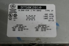
Most of the industrial control transformers I have seen have a pair of 120 volt windings on one side and a pair of 240 volt windings on the other side. Feed the low voltage side with either 120 volts (windings in parallel) or 240 volts (windings in series). The secondary is a pair of isolated 240 volt windings, which can be used independently (think circlotron) or wired in series or parallel.
I got several of these on Ebay years ago along with some 1KVA versions. The shipping costs more than the transformer. Find a seller that will stuff them into a USPS flat rate box.....your letter carrier will HATE you, but I got the transformers and the shipping for under $40 each.
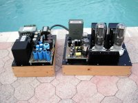
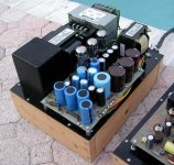
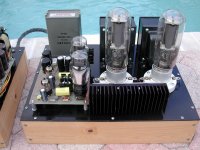
One of these runs the plate supply in my 845 SE DHT amp. It uses a voltage doubler made with 5AR4's on a 480 volt wired secondary that generates 1050 volts at 150 to 200 mA.
Attachments
I wouldn't mind cranking b+ to 650V and having a 400wpc amp
My end game if a 500WPC tube amp. Preliminary work has started, but I have to clear out some other projects first. TV sweep tubes on 650 to 700 volts will make the power. I already have the OPT's (1250 ohms) which dictate the plate voltage. The power source will likely be Antek toroids with solid state rectifiers if the SMPS experiments don't work out. The only regulation will be on the bias and screen grid supplies.
The ones I can get cheap (surplus) only have a single 120v winding as far as I can tell. If I get some that have dual, or they turn out to have it then I'll be fine. However, 1440v is assuming I stick with a halfbreed choke/capacitor input filter. Wouldn't that be quite hard on the 866As and their peak current rating? If I make a true choke input filter, wouldn't I need all 1920v? I read that a choke input filter gives an output of approximately .9 of input. In addition the 15v tube drop.
amen to that.It's because I want to.
but what kind of amplifier really needs such complicated supply ?
you know, any "nonstandard" decision costs pile of money. (but money will be not biggest problem)
- Status
- This old topic is closed. If you want to reopen this topic, contact a moderator using the "Report Post" button.
- Home
- Amplifiers
- Tubes / Valves
- Big Tube based voltage regulator