It seems to work well, but I'm not getting much airflow off of the two needles I have connected. I'm going to buy a bunch to connect and see how much air I get then  One strange thing I noticed - when touching some tin foil to the needle, and the foil to say, the table, the foil hisses loudly and seems to emit a lot of ions.. why doesn't it do this when it's floating in the air attached only to the needle? Odd!
Lots of fun was had this evening playing with sparks and high voltage!
One strange thing I noticed - when touching some tin foil to the needle, and the foil to say, the table, the foil hisses loudly and seems to emit a lot of ions.. why doesn't it do this when it's floating in the air attached only to the needle? Odd!Lots of fun was had this evening playing with sparks and high voltage!
Field gauge
Hm, I have a difficulty getting the picture here, a drawing would be nice d:
One good way to test if you have enough voltage would be to use the same electrode
materials as the lifters do; magnet wire with the enamel intact for the anode and
aluminum foil sheet for the cathode.
If the ions can pass or float above the enamel, then you have something >20.
bigwill said:It seems to work well, but I'm not getting much airflow off of the two needles I have connected. I'm going to buy a bunch to connect and see how much air I get then
Lots of fun was had this evening playing with sparks and high voltage!
Hm, I have a difficulty getting the picture here, a drawing would be nice d:
One good way to test if you have enough voltage would be to use the same electrode
materials as the lifters do; magnet wire with the enamel intact for the anode and
aluminum foil sheet for the cathode.
If the ions can pass or float above the enamel, then you have something >20.
Biefeld-Brown efect sound good but can you really prove it has better audio quality than conventional drivers?
First problem:
For a hifi audio quality you should have it extremely linear. When we talk about ionizing air it propably is not. When voltage is small the current is almost zero -> high resistance. When voltage rise the current rise even faster -> resistance drops when ions excite not-ionized air molecules. Finaly you get lightning -> resistance is low. Current vs voltage is propably something exponential?
And because current is proportional to ion flow (if every ion have the same electrical charge but it may also vary with voltage) then you have huge amount of AM-AM distortion if driven by voltage. Do you agree?
So this driver should be driven by current?
Second problem:
You move only ions. They move one direction and because of pressure difference, neutral air molecules move a bit against ions. It makes efficiency poor. Also this two-way ion&molecule movement can cause turbulence at higher voltages and higher ion flow and turbulent air is very unlinear causing distortion. So you cannot quarantee high linearity even with a current amplifier. Do you agree?
You can guarantee high linearity with voltage-to-power amplifier (an example is in one of the tubecad journals, I forget exactly which one).
In addition, if you restrict which portion of the IV curve you are operating on, you may not even need that. I've already discussed this and posted an IV cuve for all atmospheric discharge types in the old plasma threads.
In addition, if you restrict which portion of the IV curve you are operating on, you may not even need that. I've already discussed this and posted an IV cuve for all atmospheric discharge types in the old plasma threads.
Actually I had linked to the characteristic curve earlier in the thread.
http://www.diyaudio.com/forums/attachment.php?s=&postid=454537&stamp=1092096285
Dark dishcarge is only linear in a small portion. You can't use voltage- or current- out amplifier and get linearity.
http://www.diyaudio.com/forums/attachment.php?s=&postid=454537&stamp=1092096285
Dark dishcarge is only linear in a small portion. You can't use voltage- or current- out amplifier and get linearity.
42bit 96kfps Holographic Sound Project
One way to get linearity is by high bias. And with this comes the need for more voltage for the modulation, so the efficiency goes down accordingly.
An alternative could be to have a very high voltage field – there would not be much turbulence within, everything would move 'on-tracks' so to speak.
If nothing else, we could have a digitally compensated output. This wouldn't be all that difficult, and a/the holographic plasma wall should be running all–digital already
That makes sense, with the air–grounding tube.
I wonder about the specific voltages involved here.
APi said:Biefeld-Brown efect sound good but can you really prove it has better audio quality than conventional drivers?
First problem:
For a hifi audio quality you should have it extremely linear. When we talk about ionizing air it propably is not. When voltage is small the current is almost zero -> high resistance. When voltage rise the current rise even faster -> resistance drops when ions excite not-ionized air molecules. Finaly you get lightning -> resistance is low. Current vs voltage is propably something exponential?
And because current is proportional to ion flow (if every ion have the same electrical charge but it may also vary with voltage) then you have huge amount of AM-AM distortion if driven by voltage. Do you agree?
So this driver should be driven by current?
Second problem:
You move only ions. They move one direction and because of pressure difference, neutral air molecules move a bit against ions. It makes efficiency poor. Also this two-way ion&molecule movement can cause turbulence at higher voltages and higher ion flow and turbulent air is very unlinear causing distortion. So you cannot quarantee high linearity even with a current amplifier. Do you agree?
One way to get linearity is by high bias. And with this comes the need for more voltage for the modulation, so the efficiency goes down accordingly.
An alternative could be to have a very high voltage field – there would not be much turbulence within, everything would move 'on-tracks' so to speak.
If nothing else, we could have a digitally compensated output. This wouldn't be all that difficult, and a/the holographic plasma wall should be running all–digital already
bigwill said:I just had an idea for a test rig, since I don't have any suitable grid like things at the moment, I thought I might try this:
That makes sense, with the air–grounding tube.
Nixie said:Actually I had linked to the characteristic curve earlier in the thread.
http://www.diyaudio.com/forums/attachment.php?s=&postid=454537&stamp=1092096285
Dark dishcarge is only linear in a small portion. You can't use voltage- or current- out amplifier and get linearity.
I wonder about the specific voltages involved here.
42bit 96kfps Holographic Sound Project
Here is another suggestion for a transformer coupled grid.
(The grid looks like it is compressing air – the intention is
to show the need for a larger surface, so to ground the air)
Here is another suggestion for a transformer coupled grid.
(The grid looks like it is compressing air – the intention is
to show the need for a larger surface, so to ground the air)
Attachments

42bit 96kfps Holographic Sound Project
The way your transformer/grid is coupled, fed a positive audio signal is going to give attenuation – an amplitude inverter is here needed. If the anode (+) was modulated instead, then the positive signal would add to the overall voltage field, giving amplification.
It is a little strange if such a module doesn't exist somewhere within the 'modular synthesizer world' ... my old Roland guitarsynth actually had an inverted amplitude envelope function. Maybe some of the software synthesizers has this.
By the way, why is there a minus sign at the positive terminal? d:
bigwill said:I just had an idea for a test rig, since I don't have any suitable grid like things at the moment, I thought I might try this:
The way your transformer/grid is coupled, fed a positive audio signal is going to give attenuation – an amplitude inverter is here needed. If the anode (+) was modulated instead, then the positive signal would add to the overall voltage field, giving amplification.
It is a little strange if such a module doesn't exist somewhere within the 'modular synthesizer world' ... my old Roland guitarsynth actually had an inverted amplitude envelope function. Maybe some of the software synthesizers has this.
By the way, why is there a minus sign at the positive terminal? d:
42bit 96kfps Holographic Sound Project
The ground base here should be all the existing plasma transducers out there. They are certainly hi–fi devices. With miniaturization – and holographic programming, this should be able to go even one step further. If we see a problem like ozone generation, then we may instead have a really fine outdoors PA system etc. Good to see all your points though, even if they are valid
APi said:Biefeld-Brown efect sound good but can you really prove it has better audio quality than conventional drivers?
The ground base here should be all the existing plasma transducers out there. They are certainly hi–fi devices. With miniaturization – and holographic programming, this should be able to go even one step further. If we see a problem like ozone generation, then we may instead have a really fine outdoors PA system etc. Good to see all your points though, even if they are valid
Ion Wind Loudspeaker
Check the JAES article by Gerald Shirley, early 60's iirc or maybe late 50's, called "Ion Wind Loudspeaker." It's also in the Anthology I book.
I think that someone in the 80s made a large "commercial" speaker using similar technology - didn't play loud and made copious amounts of Ozone, iirc... "Toltec"?? Something with a "T" in the name, I think.
I made a little one, just a handful of needles modulated by a HV tube back around 1976... made pitifully little noise, but it was scary wideband!! Heh... little tiny bass - had to listen late at night.
Not sure if this is the same idea or not...
_-_-bear
Hrmm, I found these very relivent articles:
http://www.soteria.com/hydro/speaker1.htm
http://www.soteria.com/hydro/speaker2.htm
http://www.soteria.com/hydro/speaker1.htm
http://www.soteria.com/hydro/speaker2.htm
Re: Ion Wind Loudspeaker
These are related, the difference is the way the electrodes are implemented, in particular at the cathode. And also the addition of a grid.
This is too long a read – it would be nice if someone could give me the briefing d:
bear said:Check the JAES article by Gerald Shirley, early 60's iirc or maybe late 50's, called "Ion Wind Loudspeaker." It's also in the Anthology I book.
I think that someone in the 80s made a large "commercial" speaker using similar technology - didn't play loud and made copious amounts of Ozone, iirc... "Toltec"?? Something with a "T" in the name, I think.
I made a little one, just a handful of needles modulated by a HV tube back around 1976... made pitifully little noise, but it was scary wideband!! Heh... little tiny bass - had to listen late at night.
These are related, the difference is the way the electrodes are implemented, in particular at the cathode. And also the addition of a grid.
bigwill said:Hrmm, I found these very relivent articles:
http://www.soteria.com/hydro/speaker1.htm
http://www.soteria.com/hydro/speaker2.htm
This is too long a read – it would be nice if someone could give me the briefing d:
42bit 96kfps Holographic Sound Project
How about this one http://jnaudin.free.fr/html/vshvps.htm
bigwill said:I need to build a better power supply, my multiplier only gives out a measly 10kV, although this may be fine for experiments. Anyone got any simple circuits to get 20-30kv DC from an ignition coil?
How about this one http://jnaudin.free.fr/html/vshvps.htm
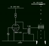
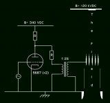
Inverter–driver, improved design
Here is a somewhat better version of the inverter–driver section.
The 5687 is a twin triode, the (x2) means 'connected in parallel'.
The value of R should be calculated to give half of
the plate current – for peace of mind
If the plate current is 12.5 mA, then 340 Volts / .0125 = 27k.
When connected in parallel this value can be used. And the
plate resistor should then be rated 10 Watts. For peace of mind again.
Attachments
- Status
- This old topic is closed. If you want to reopen this topic, contact a moderator using the "Report Post" button.
- Home
- Loudspeakers
- Planars & Exotics
- 'Biefeld-Brown effect' based full range drivers