Something that is bothering me is that the filters are ignored. They are assumed to exist, so the the signal splits between the branches, but neither the filters nor their effects are modelled in the equations. I have been thinking quite a lot about this during the past days (at least there is one good thing with insomnia ") ),but I still haven't figured out quite what this means and how it affects the whole thing. Have you considered the phase of voltages and currents in the branches, for instance?
),but I still haven't figured out quite what this means and how it affects the whole thing. Have you considered the phase of voltages and currents in the branches, for instance?
),but I still haven't figured out quite what this means and how it affects the whole thing. Have you considered the phase of voltages and currents in the branches, for instance?is Parseval's theorem related to your question?
also Christer is on to another possible issue - the biwire situation is not an exact equivalent to "mono" circuit by some "inverse superpostion " - they describe different linear systems with (slightly) dfferent linear responses
also Christer is on to another possible issue - the biwire situation is not an exact equivalent to "mono" circuit by some "inverse superpostion " - they describe different linear systems with (slightly) dfferent linear responses
Two more possible causes:
1) A speaker cable carrying current I and with a spacing d has a repulsion u.I.I/2.pi.d N/m. At 1A and d=2mm this is 10-4 N/m, which might be enough to cause the wires to move apart in the insulation. If they move then work has been done and energy absorbed.
2) A speaker cable with current flowing is a moving coil microphone. The sound from the speakers may be picked up.
Both of these effects depend on the current flowing and will be reduced by biwiring. Their significance is another matter.
poobah said:John,
Look at your equation: A^2 + 2 AB + B^2
It ain't legal to pull out the A^2 term and look at it by itself... throw in a sinewave for A and a constant for B... boil it all down and then look at A.
I have been thinking of it this way. (currents) A being AC, B being DC.
The A2 term is a result of signal A. Alone, the cable will dissipate A2Rc watts, and the load will dissipate A2RloadA watts.
The B signal will do the same by itself, producing B2Rc watts, and the load will dissipate B2RloadB watts.
When the signals are combined, each load should see the exact same dissipation it saw independently. However, the cable resistance now sees BOTH currents flowing in it at the same time. That means, the equation for the cable dissipation now has to be Rc * (A + B)2 watts. This produces the expected A2Rc term associated with the A signal and A load, the B signal term B2Rc, and as a result of the math, a 2AB Rc term..
The 2AB term of dissipation within the cable is a different time dependent function than the squared terms in the loads. Where did that time dependent power come from? The entire system power dissipation cannot change as a result of the one or two wire case, they should be equivalent as far as the amplifier can tell, the loads should dissipate the exact same thing, but yet, that 2AB term is there, dissipating at the cable..
Therein lies the issue..
Cheers, John
Christer said:Something that is bothering me is that the filters are ignored. They are assumed to exist, so the the signal splits between the branches, but neither the filters nor their effects are modelled in the equations. I have been thinking quite a lot about this during the past days (at least there is one good thing with insomnia
The reactances are completely ignored for this thought experiment. By using DC for one signal, and a high frequency for the AC, the L and C should be sufficiently low in reactance to be considered as shorts for their respective signals.
A real analysis using real components of course will be needed for testing this hypo (as phase accurate is doing), but we only get there if this infernal 2AB cannot be explained using current understanding...if it is explained away, then there's nuttin to do...is there?
However, if harmonics are generated, we have some thinking to do, don't we?
I love this stuff.
Cheers, John
Good question.jcx said:is Parseval's theorem related to your question?
Related only in that it cannot be violated. The crux of my concern is because of the conservation of energy. Since the sum dissipates more energy in the cable than the separate dissipations, the 2AB term must be taking power from elsewhere..
(Parseval's theorem states that integration of power in the time domain equals integration of power in the frequency domain)..I believe my analysis integrates to equivalence, it's the instantaneous power I am considering, which is not what Parseval's theorem states, it is integral from -infinity to +infinity.
jcx said:also Christer is on to another possible issue - the biwire situation is not an exact equivalent to "mono" circuit by some "inverse superpostion " - they describe different linear systems with (slightly) dfferent linear responses
While I do not concur, if that is indeed the case, then one has proven the case for bi-wiring, no?.
Either result is equally acceptable, as is of course the result that they are exact equivalents.. I sleep soundly regardless of the outcome of this discussion..I enjoy the discussion..thank you.
It's the journey, not the destination..
Cheers, John
davidsrsb said:Two more possible causes:
1) A speaker cable carrying current I and with a spacing d has a repulsion u.I.I/2.pi.d N/m. At 1A and d=2mm this is 10-4 N/m, which might be enough to cause the wires to move apart in the insulation. If they move then work has been done and energy absorbed.
2) A speaker cable with current flowing is a moving coil microphone. The sound from the speakers may be picked up. Both of these effects depend on the current flowing and will be reduced by biwiring. Their significance is another matter.
I had calculated the forces on a #18 guage wire a while back. With 10 amperes, no insulation (1 mm spacing), the force was .02 N/m. That is .0018 ounces per inch of wire. awfully low, and with the modulus of the insulation considered, the movement will be very small. The change in spacing which would alter the inductance of the wire needs to be very large in order to shed or store energy from the internal currents. I also did those calcs somewhere, just don't remember where..
For case 2, again, the amount of wire to wire movement must very large to generate voltage of any significance.. I suspect humans cannot survive those levels of vibration.
In any case, you have presented very good possibilities to be tested if we were trying to explain why bi-wiring changes the sound.. My analysis is using ideal components to determine how the overall system should work.
Thanks.
Cheers, John
Originally posted by phase accurate
[
A^2 + B^2 unequal (A+B)^2 Post #198
I had a deeper look at John's posting regarding the missing 2AB.
I now see what is wrong with it. He makes the wrong assumption that the audio signal follows the sum of the acoustic powers and therefore at every point down the audio-chain we would have a scaled version of the sum of acoustic power again which can be split back into seperate powers by simple linear operations.
It is not that simple though:
The signal-voltage represents the sum of sound-PRESSURE levels.
There are the same relationships between sound-power and SPL as there are between electrical power and voltage. That means for the same circumstances power raises with the square of the RMS -voltage/-SPL !
So far so good.
What happens if we now add two sinusoids of different frequency ? Is the RMS voltage of the two added signals of RMS value A and B now A+B ??? No it isn't !!!! Since they sum UNCORRELATED their new RMS value is:
SQRT(A^2 + B^2)
Now check by yourself if you would still get a missing 2AB !
BTW: If John's observations were true they would indeed have nothing to do with cables as such but they would occur in every single little part of the whole chain !
Regards
Charles
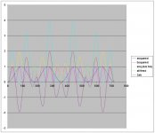
Here's a graph of the instantaneous power calculated from two sines. One at freq 1, the other at freq 3.5. both have peak value of 1.
The power of freq 1 is the dark blue line. The power of the higher freq is the pink?? line. The sum of those two is the yellow one. This represents the power dissipated in both loads, and the power that would be dissipated in separate resistors.
The purple line is the 2ab line. the bright blue one is sum of all three, Asq plus Bsq plus 2AB.
What I find really fascinating is the fact that 2AB swings plus AND minus, this represents negative power?????? Also note that the sum of all three terms NEVER goes below zero power into negative territory.
The fact that 2AB goes negative, while seemingly nonsense, remember that it in itself is an artifact of the product of the A and B, so it can never exceed in negative value, that of the two squares summed does in the positive value..In other words, it is impossible mathematically for the power to go negative..
I'd be sellin refrigerators if that were the case...and, to the king of sweden, no less..
Cheers, John
Attachments
Motor effect can be strong, if you have ever connected a jump lead between car batteries with one battery having a shorted cell so a large current flows - the cable will kick.
The microphone effect can be measurable, I tried it with 1A dc flowing and tapping the cable was visible on a scope. The magnetic field around a close pair is strong enough.
Another thought - normal strands of multistrand wire with current flowing will attract each other and this may have resistance effects. This would explain why cat5 based cables using a few conductors of individually insulated wire seem to work well for me.
davidsrsb said:Motor effect can be strong, if you have ever connected a jump lead between car batteries with one battery having a shorted cell so a large current flows - the cable will kick.
Agreed. The force goes as current squared. For current levels within a speaker wire, I think ten amps was sufficient to show the level of forces involved, and how little the wires will move.
I need this equation daily, as I typically run 1500 amps in wires that are about 16 guage, and the 50 mil spacing raises lots of forces. If I do not keep the conductors still to the tune of 50 microinches in a 2 to 5 tesla background field, they have "problems", ala "red october".
davidsrsb said:The microphone effect can be measurable, I tried it with 1A dc flowing and tapping the cable was visible on a scope. The magnetic field around a close pair is strong enough..
Again, absolutely agree. The effect of course, depends on the rate of change of the flux within the current loop, this in turn dependent on the inductance of the loop and how fast the energy sheds into the voltage produced.
What you should have done is push the amp dc into a zip cord, hook up the scope, and put it into a room where a stereo is playing loudly. That would have given you a better indication of level of effect.
davidsrsb said:Another thought - normal strands of multistrand wire with current flowing will attract each other and this may have resistance effects. This would explain why cat5 based cables using a few conductors of individually insulated wire seem to work well for me.
You are again correct...and, most people are not aware of the pinch effect. It is an issue for my work, as well as for those who use molten copper conductors in furnaces. (weird, huh?).
I suspect cat 5 issues are significantly different from what is being discussed here. Cat 5 pairs are orthogonal so inductance goes down as parallel inductors would..capacitance goes up with number of conductors..the characteristic impedance is also parallel calculated with a start at 100 ohms, 8 pair gives 12.5 ohms Zline.
Cool stuff, but not applicable to the instantaneous power issue we are discussing..
Excellent points, however..thank you.
Cheers, John
if you look closely at Parseval's theorem you will see that it claims there is no net “A*B” power over a cycle of a periodic waveform – the Fourier components are orthogonal and no net “mixed products” enter in the power spectrum
superposition done right:
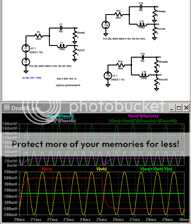
the power in each branch of the split circuit on the right doesn't add up but the sum of the Ia+b,Va+b in each image when added together do give the correct I*V - superposition works for the linear device I and V, power is not a linear function and doesn't sum when split this way
blue “V(w)*I(Rwoof)” = green “(V(wa)+V(wb))*(I(Rwoofa)+I(Rwoofb))”
the trace is just hidden under green
superposition done right:
the power in each branch of the split circuit on the right doesn't add up but the sum of the Ia+b,Va+b in each image when added together do give the correct I*V - superposition works for the linear device I and V, power is not a linear function and doesn't sum when split this way
blue “V(w)*I(Rwoof)” = green “(V(wa)+V(wb))*(I(Rwoofa)+I(Rwoofb))”
the trace is just hidden under green
Attachments
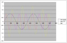
jcx said:if you look closely at Parseval's theorem you will see that it claims there is no net “A*B” power over a cycle of a periodic waveform – the Fourier components are orthogonal and no net “mixed products” enter in the power spectrum
Check out the graph. If you look carefully, the waveform is rotationally symmetric about 180 degrees. the lobes centered at 81 degrees and 284 are equal and opposite, cancelling, the lobes at 129 and 236 are also equal and opposite. (In point of fact, the period of the complex waveforn here is actually 720 degrees on the graph, but every 360 degrees has integral zero.)
So, the theorem has not been violated..the 2AB waveform is net average zero.
Where are the tweeter waveforms? From what I can see, those would be the ones changed by the 2ab power when the other signal is dc.
Re: ""the power in each branch of the split circuit on the right doesn't add up ""
That has been my contention all along..something is going on, as the power delivered by the amp and that delivered to the loads, should be identical for both cases, The monowire case should NOT be capable of causing any difference over the biwire.
Excellent..
Cheers, John
Attachments
Proper modeling
Gentlemen:
Just a couple of comments.
As I understand, this issue was brought about from comparison of separate cabling for tweeter and woofer against a common one.
If this is the case, I understand we are talking either biamplification or having the crossover network upstream of the speaker cables, as compared with the regular single cabling and passive crossover inside the box.
For the first case, the correct simulation model should be at most splitting the high pass and low pass sections, placing each in its proper branch (it doesn't matter whether they are placed before or after the cable). Otherwise, load impedance for this case is not the same as for single wiring and they cannot be compared.
With regards to the power composition issue, this frequency discrimination must also be considered. In the crossover region, i.e. at the frequency where both branches receive equal current, it is obvious the actual comparison should be with a single cable **with half the series resistance** (since for biwiring the cables are in paralell). Of course this also holds at any other frequency, I only wanted to highlight the fact that considering the same series resistance for the interconnect in both situations is wrong and will give misleading results when computing power (de)composition.
With respect to jcx simulation, it is correct nonwithstanding said above, in the sense of showinghow superposition holds for linear systems.
Rodolfo
Re: Proper modeling
The comment about the power not adding up is the inconsistency I keep coming back to. Using one cable with the appropriate resistance should be equivalent to the two. This includes all power transferred and lost.
Cheers, John
ps..welcome to the thread, your name is unfamiliar to me..
Yesingrast said:As I understand, this issue was brought about from comparison of separate cabling for tweeter and woofer against a common one.
Not biamp, just the difference between a single cable feeding the crossover and two cables, each dedicated to it's portion of the crossover.ingrast said:If this is the case, I understand we are talking either biamplification or having the crossover network upstream of the speaker cables, as compared with the regular single cabling and passive crossover inside the box.
Agreed.ingrast said:For the first case, the correct simulation model should be at most splitting the high pass and low pass sections, placing each in its proper branch (it doesn't matter whether they are placed before or after the cable). Otherwise, load impedance for this case is not the same as for single wiring and they cannot be compared.
Agreed. to keep the analysis simple, I used a DC component and an AC one, to remove the crossover region interaction out of the mix, so to speak.ingrast said:With regards to the power composition issue, this frequency discrimination must also be considered. In the crossover region, i.e. at the frequency where both branches receive equal current, it is obvious the actual comparison should be with a single cable **with half the series resistance** (since for biwiring the cables are in paralell). Of course this also holds at any other frequency, I only wanted to highlight the fact that considering the same series resistance for the interconnect in both situations is wrong and will give misleading results when computing power (de)composition.
ingrast said:With respect to jcx simulation, it is correct nonwithstanding said above, in the sense of showinghow superposition holds for linear systems.Rodolfo
The comment about the power not adding up is the inconsistency I keep coming back to. Using one cable with the appropriate resistance should be equivalent to the two. This includes all power transferred and lost.
Cheers, John
ps..welcome to the thread, your name is unfamiliar to me..
Re: Re: Proper modeling
Please sketch the circuit where you find power inconsistencies.
Rodolfo
jneutron said:...The comment about the power not adding up is the inconsistency I keep coming back to. Using one cable with the appropriate resistance should be equivalent to the two. This includes all power transferred and lost...
Please sketch the circuit where you find power inconsistencies.
Rodolfo
Re: Re: Re: Proper modeling
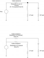
Top is single cable, both currents flow through the one wire.
Bottom is bi-wire. Each current flows through it's respective cable.
John
Here are the two circuits. sorry it'll take two posts to explain.ingrast said:
Please sketch the circuit where you find power inconsistencies.
Rodolfo
Top is single cable, both currents flow through the one wire.
Bottom is bi-wire. Each current flows through it's respective cable.
John
Attachments
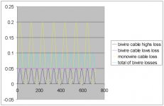
This is the graph of the dissipations.
The dark blue is the hf dissipation within the biwire setup.
The red? is the lf dissipation within the biwire setup. DC for simplicity.
the Light blue is the sum of the two power dissipations in the biwire case.
The Yellow is the dissipation within the cable for both the low and hf signals present within the resistor.
The difference is the 2AB term of the equation, this I stated in post #28.
(A + B)[sup2[/sup] = A2 + 2AB + B2
There should be no difference.
This model used .05 ohms cable, 1 amp dc, 1 amp peak ac, 8 ohm loads..each load gets 8 watts of power.
The scale is in watts.
The difference in peak wattage loss is 100 milliwatts, .1watt/8watts is 1.25 % difference. That is the difference between the yellow and the light blue waveform.
Cheers, John
Attachments
Hi Jn,
can you confirm that the graphs shown in post37 are not sinusoidal?
It appears that the rms power loss in the hi only graph is about 0.015 to 0.02 watts.
If you add the low loss =0.05W and the high loss then the total= 0.065W to 0.07W based on visual rms estimation.
If the total loss of the combined cable were also at this range then your equivalence is established. The total graph losses are substantially below 0.1W. It appears to me that the numbers are very close.
Now considering superposition, the instantaneous currents in the combined cable will predict accurately the voltage losses in the cable. This instantaneous addition will also show the voltage intermodulation that the two speakers suffer from when run on a combined cable with actual resistance. (i don't know how to examine the impedance case).
Could the differences you are finding be phase differences where the two loads have leading and lagging currents with respect to the drive voltage?
I don't see why John is interested in how INSTANTANEOUS power adds at all.
Instantaneous power carries no energy because it's duarion time is zero. I therefore doubt the validity of any conlcusions taken from it.
In order to represent energy instanataneous power has to be integrated over time. And it has to be done over an integer amount of signal periods (making it a little inconvenient for non-integer frequency ratios).
As John already found out the 2AB term is changeing between positive and negative and is therefore averaging out to zero.
Regards
Charles
Hi Phase,
why should power be related to time?
P=IV and this holds true for any time period, however short or long. Peak power is just such a short term case
I said
My comment
why should power be related to time?
P=IV and this holds true for any time period, however short or long. Peak power is just such a short term case
I said
andinstantaneous currents
I did not refer to instantaneous power.voltage losses
My comment
was an alternative approach to understanding the problem since the rest of you are getting tied in knots as you all go down the same plug hole. I'm not too good at lateral thinking but just trying to help.instantaneous addition will also show the voltage intermodulation
- Status
- This old topic is closed. If you want to reopen this topic, contact a moderator using the "Report Post" button.
- Home
- Design & Build
- Parts
- Bi wiring/single wire distortion thread