Omicron said:Hi John,
Pretty basic stuff it seems to me.
Nowhere in your experiment, and i really mean NOWHERE, is there ANY voltage that is not EXACTLY the same shape as the currents that are flowing. Hence there is NO DISTORTION! To claim otherwise is to reject ohm's law. It's as simple as that.
Best regards,
Kurt
As a current fed system, the load voltages will be exactly as expected, and will be exactly the same for the cases of biwire and monowire. The drop across the resistor, however, is different, as expected.
I note that there has been concern over the use of a 50 milliohm resistor for the biwire cable resistances, and using the exact same resistor for the monowire case. the single 50 milliohm one is being used. This equates the systems for either hf or dc. It is a simple exercise to change the monowire resistance in an attempt to equate the two, but it never results in the same dissipation vs time profile.
Don't worry, I'm not violating any laws ohm, joule, or thermo.
.. In fact, those are used to test the validity of the model. (after all, I'm not nuts, even though you may be having your doubts..
") )
)How then, how do you consolidate the factor of 2 peak power vs the biwire setup when the orthogonal currents are flowing through the single resistor? Energy must be conserved within the system, even if one must integrate over differential time. You are ignoring the difference in instantaneous power dissipation between the two cases while I consider that to be the crux of the matter.
I have some guys here workin on this also. So far, we have not been able to eliminate amplitude modulation of the hf sine by the dc...on the blackboard. I present my assertion and we work to shoot it down..quite like we are doing here..
What stands out for me, is that if amplitude modulation of the hf is produced, why has it never been seen? ever? That would tend to reduce the likelyhood of my premise even more, no? They do not exist, or we have failed to find it. The loop voltages also do not help, they are entirely consistent with existing theory.
I continue work, as I enjoy the challenge.. I am not one of the people who simply accept what was taught. There are reasons for everything. I will find why my premise is incorrect, or I will find out how the different dissipation presents itself..
it is a fun exercise..as is the discussion with you..thanks..
Cheers, John
jneutron said:
How then, how do you consolidate the factor of 2 peak power vs the biwire setup when the orthogonal currents are flowing through the single resistor? Energy must be conserved within the system, even if one must integrate over differential time. You are ignoring the difference in instantaneous power dissipation between the two cases while I consider that to be the crux of the matter.
Well my point is that you can't compare the two cases in the way you are doing. Power dissipated in the wire is not equal in both circuits because they are, well...different circuits! The "extra" power dissipated in one case simply comes from the amp who has to pump more power in that circuit to satisfy the condition you imposed, i.e. that the power in the loads remain the same (you imposed this by choosing current sources to drive your circuits).
You're really comparing apples and oranges here.
On top of that your argument rests on an absurdity: i.e. on the one hand you postulate an experiment that keeps the currents trough the loads identical for mon- and bi- wire cases. Yet then you assume that some "error voltage" must develop somewhere that affects these same loads! Which, if true, obviously only proves only that the currents trough the loads CANNOT satisfy your intial postulate (exept when you trash ohm's law off course)...
Omicron said:
Well my point is that you can't compare the two cases in the way you are doing. Power dissipated in the wire is not equal in both circuits because they are, well...different circuits! The "extra" power dissipated in one case simply comes from the amp who has to pump more power in that circuit to satisfy the condition you imposed, i.e. that the power in the loads remain the same (you imposed this by choosing current sources to drive your circuits).
I chose current sources to simplify understanding.
In a linear system, the power profile of the wire dissipation is exactly the same as that of the load. This is indeed the case for the biwire system.
When the two signals are combined into the single wire, and branch at the load, the power profile of the wire dissipation is different. It is not the sum of the two individuals, it has the additional component.
You cannot turn the amp up to compensate for the change in dissipation, it is not there for the individual circuits. Yes, you can make the rms values consistent, but the time varying dissipation will not be identical, and you cannot make is so.
Can you show mathematically how the time varying dissipation is the same vs time for the two cases? I would like to see that. Stating that I am violating ohms law does not clarify your objection. Please show how the system compensates for the power loss in the resistor.
Omicron said:
On top of that your argument rests on an absurdity: i.e. on the one hand you postulate an experiment that keeps the currents trough the loads identical for mon- and bi- wire cases. Yet then you assume that some "error voltage" must develop somewhere that affects these same loads! Which, if true, obviously only proves only that the currents trough the loads CANNOT satisfy your intial postulate (exept when you trash ohm's law off course)...
You are not clear in understanding what I have stated. Perhaps my fault..
With a current drive, the loads will receive identical signals. And the issue of resistor dissipation is very clearly I * I * R. Any difference will show at the source node.
With a voltage drive, the loads will not receive identical signals, and the dissipation will be a function of the loop currents, which are dependent on the drops. The source node current will be different.
You must keep the scenarios independent.
It is easier to understand the current drive scenario. It is easier to test the voltage drive one.
With my argument several absurdities exist..I pose an argument that seems to provide non linearities within a linear circuit..I pose a result that has not been measured..
An RMS power based explanation is certainly insufficient to refute my argument.
Try working out the resistor dissipations vs time, for both wire schemes, and point out exactly why the factor of 2 difference in peak dissipation across the cable resistor does not upset the applecart, so to speak..
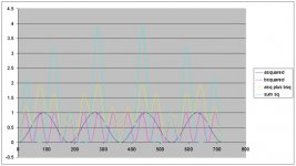
The blue curve is the power dissipated for two orthogonal sines, the yellow is what is dissipated in the biwire case..
The amplifier gain cannot change this profile..
Cheers, John
Attachments
Well, in both cases all power must come from the amplifier, so we can always write:
Pamplifier = Pa + Pb + Plosses
These are not RMS values but power at each instant of time.
The other constraint we have is that currents A and B are kept constant.
Consider the mono-wire case:
Pamplifier = sq(A)Ra + sq(B)Rb + sq(A)Rc + sq(B)Rc + 2ABRc
Consider the bi-wire case:
Pamplifier = sq(A)Ra + sq(B)Rb + sq(A)Rc + sq(B)Rc
These equations are also valid for power at any point in time.
For both situations the power in the loads is always ARa and BRb (this in itself should be sufficient to understand that there is no distortion).
So, what this tells me is simply that the amplifier is not delivering the same amount of power in each case. Hence the 2ABRc term cannot "upset" anything. It just expresses the fact that the mono-wire case has more wire losses which the amplifier will have to overcome if the same currents are to be maintained (i.e. the voltage levels produced by the amp will have to be higher). For a real amp this is going to mean you'll have to adjust the volume setting (once) when going from one configuration to the other or the power in the loads will not be the same.
So, I don't see any mysteries here. Not a single contradiction. I have already shown that the 2ABRc term can exist without causing any "new" frequencies in the spectrum of I or V.
jneutron said:
The amplifier gain cannot change this profile..
The gain can't but you forget that DC offset CAN! Think about what happens to the wave shape of the power when you send a sine wave trough a resistor and then change it's DC component. You'll see a plethora of different shapes as you vary the DC offset.
And the DC offsets in the Rc wires in both cases are not equal (as one leg in the bi-wire case doesn't have one).
What is needed is to look at the system in segments, divided by an arbitrary line.Omicron said:Well, in both cases all power must come from the amplifier, so we can always write:
Pamplifier = Pa + Pb + Plosses
These are not RMS values but power at each instant of time.
The other constraint we have is that currents A and B are kept constant.
Consider the mono-wire case:
Pamplifier = sq(A)Ra + sq(B)Rb + sq(A)Rc + sq(B)Rc + 2ABRc
Consider the bi-wire case:
Pamplifier = sq(A)Ra + sq(B)Rb + sq(A)Rc + sq(B)Rc
These equations are also valid for power at any point in time.
For both situations the power in the loads is always ARa and BRb (this in itself should be sufficient to understand that there is no distortion).
So, what this tells me is simply that the amplifier is not delivering the same amount of power in each case. Hence the 2ABRc term cannot "upset" anything. It just expresses the fact that the mono-wire case has more wire losses which the amplifier will have to overcome if the same currents are to be maintained (i.e. the voltage levels produced by the amp will have to be higher). For a real amp this is going to mean you'll have to adjust the volume setting (once) when going from one configuration to the other or the power in the loads will not be the same.
So, I don't see any mysteries here. Not a single contradiction. I have already shown that the 2ABRc term can exist without causing any "new" frequencies in the spectrum of I or V.
If one uses biwiring, select the segmentation to be between the amp and the cable plus loads.
Look at the amp which has A+B as an out, with it's dissipation of (a+b)2, while the load is split into two squares only.
Vs the monowire case, where one must set the segmentation AT THE branch juncture.
By segmenting at the juncture, the amp AND the wire both share the exact same power profile, while the load has the same one as always.
Where I was unable to consolidate the different power profiles was solely determined by where that segmentation occurs.
This view now squares entirely with what we were taught, and is consistent with what you have been stating..
I am now happy...and can easily reject the hypothesis that the selection of wiring scheme alters the signals via the 2ab component of a mixed signal power profile..perhaps in the near future, when I have my workshop back up, I will endeavor to do a test setup to confirm what we already understand..
Course, there are a few people who were on the railroad with me who were concerned with my sanity..did you realize that kinetic energy, gravometric potential, capacitor and inductor energy equations all share the same constructs as resistor dissipation?...(it is scary when I am given free time to dwell on this goop).
Kurt (and all others), it has been a distinct pleasure..thank you for your time and patience..
Cheers, John
- Status
- This old topic is closed. If you want to reopen this topic, contact a moderator using the "Report Post" button.